background image

7

Status error of drive (0: No failure 1: Failure)

Upper communication connection status (0: No failure 1: Failure)

Reserved, default 0

Reserved, default 0

Reserved, default 0

Reserved, default 0

Reserved, default 0

Reserved, default 0

Battery under-voltage failure (0: No failure 1: Failure)

Reserved, default 0

Remote control loss protection (0: No failure 1: Failure)

Steering motor drive communication failure (0: No failure 1: Failure)

Rear right motor drive communication failure (0: No failure 1: Failure)

Rear left motor drive communication failure (0: No failure 1: Failure)

Reserved, default 0

Front wheel steering encoder disconnection failure (0: No failure 1: Failure)

byte [4]

byte [5]

Byte

Bit

Meaning

Sending node

Steer-by-wire chassis

Data length

Position

byte [0]

byte [1]

Receiving node

Decision-making control unit

0×08

Function

Current status of

 chassis body

Mode control

ID

0x211

Data type

unsigned int8

unsigned int8

                   Cycle (ms) 

                    Receive-timeout (ms)

                      100ms 

                    None

Description

0×00 System in normal condition

0×01 Emergency stop mode (not enabled)

0×02 System exception

byte [2]

byte [3]

byte [4]

byte [5]

Battery voltage higher 8 bits

Battery voltage lower 8 bits

Failure information higher 8 bits

Failure information lower 8 bits

unsigned int16

unsigned int16

byte [6]

byte [7]

Parking(brake) state

Parity bit (checksum)

unsigned int8

unsigned int8

Actual voltage × 10 (with an accuracy of 0.1V)

See notes for details

[Description of Failure Information]

0×00 Standby mode

0×01 CAN command control mode

0×02 Remote control mode

0×00 Brake unlocked state   0×01 Brake locked state

00-255 counting loops, which will be 

added once every command sent

Table 3.1 Feedback Frame of HUNTER 2.0 Chassis System Status

System Status Feedback Frame

Command Name

Description of Failure Information

bit [0]

bit [1]

bit [2]

bit [3]

bit [4]

bit [5]

bit [6]

bit [7]

bit [0]

bit [1]

bit [2]

bit [3]

bit [4]

bit [5]

bit [6]

bit [7]

Summary of Contents for HUNTER 2.0

Page 1: ...AgileX Robotics Team HUNTER 2 0 User Manual 2021 03 V 2 1 0...

Page 2: ...ead and understand this information before using the device If you have any questions about use please contact us at support agilex ai Please follow and implement all assembly instructions and guideli...

Page 3: ...nd the basic operating content and operating speci ca tion No passengers For remote control operation select a relatively open area to use HUNTER 2 0 because HUNTER 2 0 is not equipped with any automa...

Page 4: ...d operation 3 2 Charging and battery replacement 3 3 Communication using CAN 3 3 1 CAN message protocol 3 3 2 CAN cable connection 3 3 3 Implementation of CAN command control control 3 4 Firmware upgr...

Page 5: ...eral logistics and transportation FS RC transmitter is provided optional in the factory setting pf HUNTER 2 0 which allows users to control the chassis of robot to move and turn CAN and RS232 interfac...

Page 6: ...unted at the rear end of chassis body which can shut down power of the robot immediately when the robot behaves abnormally Water proof connectors for DC power and communication interfaces are provided...

Page 7: ...attention to battery recharging during use 2 1 Status indication 2 2 Instructions on electrical interfaces Voltage Replace battery Robot powered on The current battery voltage can be read from the vo...

Page 8: ...wo of them are internally inter connected The pin de nitions are given in Figure 2 7 2 2 2 Rear electrical interface Figure 2 6 Rear View Figure 2 5 Description of Top DB9 interface Figure 2 7 Descrip...

Page 9: ...he right the car will turn to the right and push it to the maximum at this time the right steering angle is the largest In the control command mode the positive value of the linear velocity means move...

Page 10: ...king command When the emergency stop is triggered the parking will automatically start At this time released the emergency stop no matter where the remote control SWA is located it needs to be unlocke...

Page 11: ...atus of chassis body Mode control ID 0x211 Data type unsigned int8 unsigned int8 Cycle ms Receive timeout ms 100ms None Description 0 00 System in normal condition 0 01 Emergency stop mode not enabled...

Page 12: ...bits Reserved Reserved Reserved Reserved Corner higher 8 bits Corner lower 8 bits ID 0x221 Data type signed int16 signed int16 Cycle ms Receive timeout ms 20ms None Description Actual speed 1000 with...

Page 13: ...eering encoder communication failure 0 07 Clear remote control signal loss failure Command Name Status Setting Command Cycle ms None Receive timeout ms None Note Example data The following data is onl...

Page 14: ...nt16 signed int16 signed int8 unsigned int8 Unit 1 C See the details in Drive control status 0x00 0x00 Motor Drive Low Speed Information Feedback Frame Command Name Description Current voltage of driv...

Page 15: ...31 Date type unsigned int8 Description 0 00 Turn o parking unlock the brake 0 01 Turning on parking lock the brake The brake need to be unlocked to control the speed of the chassis Command Name Parkin...

Page 16: ...ileometer lowest bit Right wheel mileometer highest bit Right wheel mileometer second highest bit Right wheel mileometer second lowest bit Right wheel mileometer lowest bit Command Name Mileage Feedba...

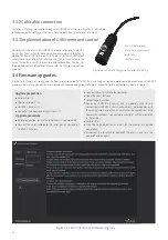
Page 17: ...o Table 3 2 3 3 2 CAN cable connection 3 3 3 Implementation of CAN command control 3 4 Firmware upgrades Figure 3 2 Schematic Diagram of Aviation Male Plug Figure 3 3 Client Interface of Firmware Upgr...

Page 18: ..._ros code cd catkin_ws src git clone https github com agilexrobotics hunter_2_ros git git clone https github com agilexrobotics agx_sdk git cd catkin_ws catkin_make Please refer to https github com ag...

Page 19: ...ttery storage is 10 to 45 in case of storage for no use the battery must be recharged and discharged once about every 2 months and then stored in full voltage state Please do not put the battery in re...

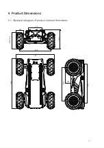
Page 20: ...6 Product Dimensions 6 1 Illustration diagram of product external dimensions 16 980 745 760 105 650 375 140 330 13in 270 605...

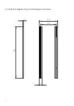
Page 21: ...6 2 Illustration diagram of top extended support dimensions 17 16 760 230 270 40...

Page 22: ...AgileX Robotics CO Ltd TEL 86 769 22892150 WWW AGILEX AI Email sales agilex ai...

Reviews: