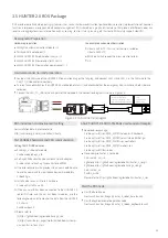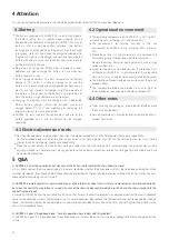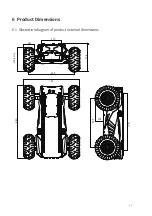
The mode setting frame is use to set the control interface of HUNTER 2.0. The detailed content of the protocol is as follows.
9
Sending node
Decision-making control unit
Date length
Position
byte [0]
Receiving node
Chassis node
0×01
Function
Control mode
ID
0x421
Date type
unsigned int8
Description
0×00 Standby mode
0×01 CAN command mode
Power-on enters standby mode default
Command Name
Control Mode Setting Command
Cycle (ms)
None
Receive-timeout (ms)
None
Sending node
Decision-making control unit
Date length
Position
byte [0]
Receiving node
Chassis node
0×01
Function
Errors clearing command
ID
0x441
Date type
unsigned int8
Description
0×00 Clear all not serious failure
0×01 Clear steering motor drive communication failure
0×02 Clear rear right motor drive communication failure
0×03 Clear rear left motor drive communication failure
0×05 Clear battery under-voltage failure
0×06 Clear steering encoder communication failure
0×07 Clear remote control signal loss failure
Command Name
Status Setting Command
Cycle (ms)
None
Receive-timeout (ms)
None
[Note] Example data: The following data is only used for testing
1.The chassis moves forward at 0.15m/s ( It need to unlock parking by command before running)
2.The chassis steering 0.2rad
byte [0] byte [1] byte [2] byte [3] byte [4] byte [5] byte [6] byte [7]
0x00
0x00 0x00
0x00
0x00 0x00
0x00 0xC8
byte [0] byte [1] byte [2] byte [3] byte [4] byte [5] byte [6] byte [7]
0x00
0x96 0x00 0x00
0x00 0x00
0x00 0x00
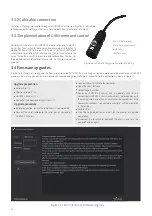
Description of control mode: In case the HUNTER 2.0 is powered on and the RC transmitter is not connected, the control mode is defaulted
to standby mode. At this time, the chassis only receives control mode command, and does not respond other commands. To use CAN for
control need to switch CAN command mode at first. If the RC transmitter is turned on, the RC transmitter has the highest authority, can
shield the control of command and switch the control mode.
Status setting frame is use to clear the system errors. The detailed content of the protocol is as follows.


