Correctly start the chassis of HUNTER 2.0 mobile robot, and turn on RC
transmitter. Then, switch to the command control mode, i.e. toggling S1
mode of RC transmitter to the top. At this point, HUNTER 2.0 chassis will
accept the command from CAN interface, and the host can also parse the
current state of chassis with the real-time data fed back from CAN bus. For
the detailed content of protocol, please refer to CAN communication
protocol.
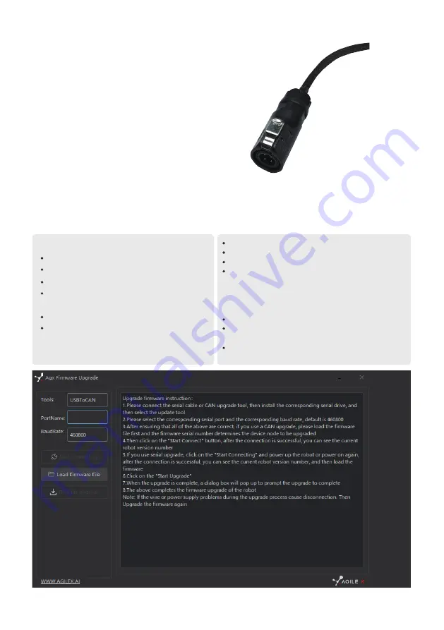
In order to facilitate users to upgrade the firmware version used by HUNTER 2.0 and bring customers a more complete experience, HUNTER 2.0
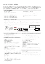
provides a firmware upgrade hardware interface and corresponding client software. A screenshot of this application is shown in Figure 3.3.
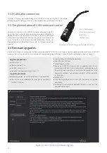
2 aviation male plugs are supplied along with HUNTER 2.0 as shown in Figure 3.2. Users need
to lead wires out by welding on their own. For wire definitions, please refer to Table 3.2.
3.3.2 CAN cable connection
3.3.3 Implementation of CAN command control
3.4 Firmware upgrades
Figure 3.2 Schematic Diagram of Aviation Male Plug
Figure 3.3 Client Interface of Firmware Upgrade
RED :VCC(positive pole)
BLACK :GND(negative pole)
BLUE :CAN_L
YELLOW :CAN_H
Connect the serial cable to the computer;
Open the client software;
Select the port number;
Power on HUNTER 2.0 chassis, and immediately click to start
connection (HUNTER 2.0 chassis will wait for 3s before power-on; if
the waiting time is more than 3s, it will enter the application); if the
connection succeeds, "connected successfully" will be prompted
in the text box;
Load Bin file;
Click the Upgrade button, and wait for the prompt of upgrade
completion;
Disconnect the serial cable, power off the chassis, and turn the
power off and on again.
Before connection, ensure the robot chassis is powered off;
Connect the serial cable onto the serial port at rear end of
HUNTER 2.0 chassis;
Upgrade procedure
Upgrade preparation
Serial cable × 1
USB-to-serial port × 1
HUNTER 2.0 chassis × 1
Computer (Windows operating system) × 1
13


