323
2467S–AVR–07/09
ATmega128
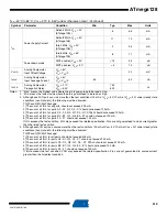
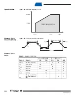
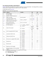
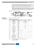
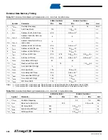
5. This requirement applies to all ATmega128 Two-wire Serial Interface operation. Other devices
connected to the Two-wire Serial Bus need only obey the general f
SCL
requirement.
6. The actual low period generated by the ATmega128 Two-wire Serial Interface is (1/f
SCL
- 2/f
CK
),
thus f
CK
must be greater than 6 MHz for the low time requirement to be strictly met at f
SCL
=
100 kHz.
7. The actual low period generated by the ATmega128 Two-wire Serial Interface is (1/f
SCL
- 2/f
CK
),
thus the low time requirement will not be strictly met for f
SCL
> 308 kHz when f
CK
= 8 MHz. Still,
ATmega128 devices connected to the bus may communicate at full speed (400 kHz) with other
ATmega128 devices, as well as any other device with a proper t
LOW
acceptance margin.
Figure 154.
Two-wire Serial Bus Timing
SPI Timing
Characteristics
and
for details.
Note:
1. In SPI Programming mode the minimum SCK high/low period is:
- 2 t
CLCL
for f
CK
< 12 MHz
- 3 t
CLCL
for f
CK
>12 MHz
t
SU;STA
t
LOW
t
HIGH
t
LOW
t
of
t
HD;STA
t
HD;DAT
t
SU;DAT
t
SU;STO
t
BUF
SCL
SDA
t
r
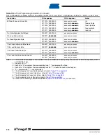
Table 134.
SPI Timing Parameters
Description
Mode
Min
Typ
Max
1
SCK period
Master
See
ns
2
SCK high/low
Master
50% duty cycle
3
Rise/Fall time
Master
3.6
4
Setup
Master
10
5
Hold
Master
10
6
Out to SCK
Master
0.5 • t
sck
7
SCK to out
Master
10
8
SCK to out high
Master
10
9
SS low to out
Slave
15
10
SCK period
Slave
4 • t
ck
11
SCK high/low
Slave
2 • t
ck
12
Rise/Fall time
Slave
1.6
µs
13
Setup
Slave
10
ns
14
Hold
Slave
10
15
SCK to out
Slave
15
16
SCK to SS high
Slave
20
17
SS high to tri-state
Slave
10
18
SS low to SCK
Slave
2 • t
ck


