DL205 Analog Manual, 7th Edition Rev. D
11-18
Chapter 11: F2-08DA-2, 8-Channel Analog Voltage Output
1
2
3
4
5
6
7
8
9
10
11
12
13
14
A
B
C
D
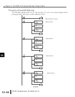
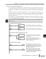
Write Data to One Channel
The following example can be used if only one channel is to be written to, or if the outputs
are to be controlled individually. Don’t forget to either embed the sign information or use the
sign output bit for bipolar ranges.
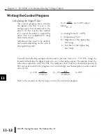
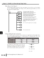
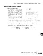
Analog and Digital Value Conversions
It is sometimes useful to do quick conversions between the signal levels and the digital values.
This can be helpful during startup or troubleshooting. The following table shows some
formulas to help with the conversions.
For example, if a 0–10V range is used, and a 6V
signal level is needed, use the formula to the right
to determine the digital value “D” to be stored in
the V-memory location which contains the data.
Chapter 11: F2-08DA-2, 8-Channel Analog Voltage Output
1
2
3
4
5
6
7
8
9
10
11
12
13
14
A
b
C
D
Range
If the digital value is known
If the analog signal level is known.
0 – 10V
A = 10D
4095
D = 4095 (A)
10
0 – 5V
A = 5D
4095
D = 4095 (A)
5
D = 4095 (A)
10
D = 4095 (6V)
10
D = (409.5) (6)
D = 2457
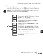
BIN
SP1
LD
V2000
OUT
V40501
The LD instruction loads the data into the
accumulator. Since SP1 is used, this rung
automatically executes on every scan. You could
also use an X, C, etc. permissive contact.
The BIN instruction converts the accumulator data
to binary (you must omit this step if you have
already converted the data elsewhere).
ANDD
K0FFF
The ANDD instruction masks off the channel select
bits to prevent an accidental channel selection.
The OUT instruction sends the data to the module. Our
example starts with V40501, but the actual value
depends on the location of the module in your
application.
RST
Y34
OUT
Y37
Y37 is the output enable bit.
RST
Y36
Y34, Y35, Y36--OFF selects channel 1 for updating.
RST
Y35
Summary of Contents for DL205
Page 1: ...DL205 Analog I O Manual Manual Number D2 ANLG M ...
Page 2: ...Notes ...
Page 6: ...Notes ...


