DL205 Analog Manual, 7th Edition Rev. D
16-16
Chapter 16: F2-8AD4DA-2, 8-Ch. In / 4-Ch. Out Analog Voltage Combination
1
2
3
4
5
6
7
8
9
10
11
12
13
14
15
16
C
D
1
2
3
4
5
6
7
8
9
10
11
12
13
14
15
16
C
D
Writing the Control Program
Configuring the Module to Read/Write I/O
(Pointer Method, DL250-1 and DL260 only)
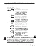
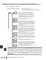
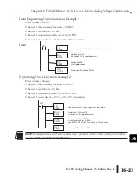
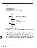
The example programs starting on the facing page show how to configure the special
V-memory locations to read/write data from/to the I/O module. The module configuration
rung needs to be read by the CPU only after a mode transition, and does not need to be read
every scan. Place the configuration rung anywhere in the ladder program, or in the initial stage
if stage programming instructions is being used. This is all that is required to read the input
data and write the output data to/from the V-memory locations. Once the input data is in
V-memory, math can be used for data calculations, compare the data against preset values,
and so forth.
V2000 and V2020 are used as the beginning of the data areas in the example, but any user
V-memory locations can be used. Also, these examples assume that the module is installed
in slot 3 of the CPU base. The pointer V-memory locations determined by the layout of the
application should be used.
Summary of Contents for DL205
Page 1: ...DL205 Analog I O Manual Manual Number D2 ANLG M ...
Page 2: ...Notes ...
Page 6: ...Notes ...

