Chapter
Ⅱ
G Commands
55
Ⅰ
Programming
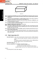
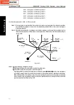
Note 1: After G50 changes the workpiece coordinate system, other workpiece coordinate system also
performs the same offset;
Note 2: In G50, the system can omit one or all command addresses for each axis, the current coordinate
value is not input when the command value for each axis is not input. When the axis command
address is omitted, the coordinate axis which is not input keeps its pervious coordinate value;
Note 3: When G50 and G command (G00, G01) are in the same block, the system only modifies the modal
value of Group 1, and the coordinate value in the block is specified by G50;
Note 4: When the system does not set G50 offset value, it can set No. 1202 Bit(G50) to forbid G50;
Note 5: After G50 sets the coordinate system, the system must be turned off and then on, the coordinate
values set by G50 remain unchanged before power off.
Note 6: In NC program, when LGT is set the coordinate offset mode to execute the tool offset, and the
system executes T function does not execute the absolute value command, the coordinate system
is set by G50, the absolute coordinate value displayed by G50 is the one that the coordinate value
set by G50 adding the tool compensation value which is not executed. The difference between the
relative coordinates and the machine coordinates is
(
-80
,
10
)
when the system executes N4, the
difference value is caused because X100Z10 setting G50X20Z20 to create the workpiece
coordinate system offset, i.e. the user does not think over the tool offset influence when G50 is set
in NC program.
Program
Absolute
coordinate
Relative
coordinate
Machine
coordinate
N1 T0100 G00 X100 Z10
X
:
100 Z
:
10 X
:
100 Z
:
10 X
:
100 Z
:
10
N2 T0101
(
No.01 tool
compensation value X12
Z23
)
X
:
88 Z
:
-13
X
:
100 Z
:
10 X
:
100 Z
:
10
N3 G50 X20 Z20
X
:
8 Z
:
-3 X
:
20 Z
:
20 X
:
100 Z
:
10
N4 G00 X10 Z10
X
:
10 Z
:
10 X
:
22 Z
:
33 X
:
102 Z
:
23
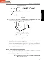
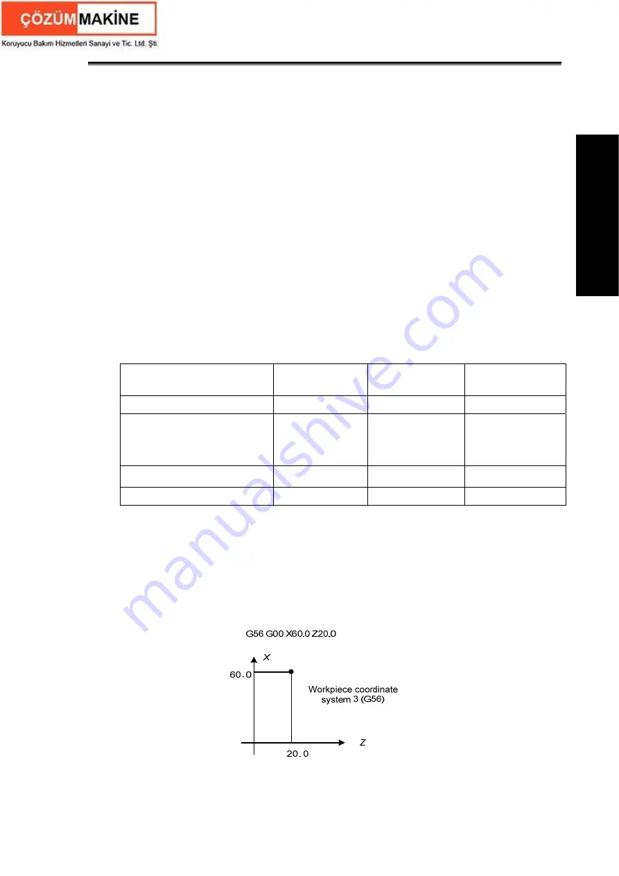
2.13.3 Workpiece coordinate system selection command G54
~
G59
Command function
: One of G54
~
G59 is specified, one of workpice coordinate system 1
~
6
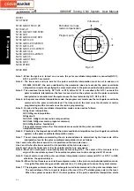
can be selected. After the workpiece coordinate system is specified,
the specified point in the block is in the specified workpiece till a new
workpiece coordinate system is created as Fig. 2-21. The tool positions
X60.0, Z20.0 in the workpiece coordinate system 3.
Fig. 2-22
Command format
:
G54 workpiece coordinate system 1
;
Summary of Contents for 988T
Page 6: ...GSK988T Turning CNC System User Manual VI ...
Page 14: ...GSK988T Turning CNC System User Manual XIV ...
Page 15: ...Chapter 1 Programming Fundamentals 1 Ⅰ Programming Ⅰ PROGRAMMING ...
Page 16: ...GSK988T Turning CNC System User Manual 2 Ⅰ Programming ...
Page 194: ...GSK988T Turning CNC System User Manual 180 Ⅰ Programming ...
Page 195: ...Chapter Ⅰ Overview 181 Ⅱ Operation Ⅱ OPERATION ...
Page 196: ...GSK988T Turning CNC System User Manual 182 Ⅱ Operation ...
Page 217: ...Chapter Ⅲ Windows 203 Ⅱ Operation ...
Page 267: ...Chapter Ⅲ Windows 253 Ⅱ Operation Fig 3 51 Fig 3 52 ...

