Nations Technologies Inc.
Tel
:
+86-755-86309900
:
info@nationstech.com
Address: Nations Tower, #109 Baoshen Road, Hi-tech Park North.
Nanshan District, Shenzhen, 518057, P.R.China
252
/
631
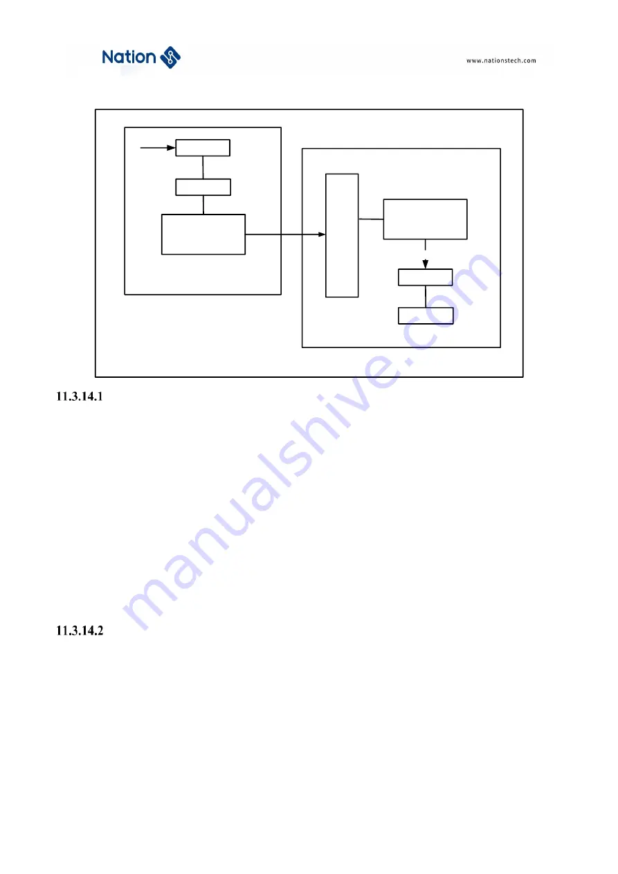
Figure 11-22 Block diagram of timer interconnection
Master timer as a prescaler for another timer
TIM1 as a prescaler for TIM2. TIM1 is maser, TIM2 is slave.
User need to do the following steps for this configuration.
Setting TIM1_CTRL2.MMSEL=’ 010’ to use the update event of TIM1 as trigger output.
Configure TIM2_SMCTRL. TSEL= ‘000’ , connect the TRGO of TIM1 to TIM2.
Configure TIM2_SMCTRL.SMSEL = ‘111’, the slave mode controller will be configured in external clock
mode 1.
Start TIM2 by setting TIM2_CTRL1. CNTEN = ‘1’.
Start TIM1 by setting TIM1_CTRL1. CNTEN = ‘1’.
Note: If user select OCx as the trigger output of TIM1 by configuring MMSEL = ‘1xx’, OCx rising edge will be used
to drive timer2.
Master timer to enable another timer
In this example, TIM2 is enabled by the output compare of TIM1. TIM2 counter will start to count after the OC1REF
output from TIM1 is high. Both counters are clocked based on CK_INT via a prescaler divide by 3 is performed
(f
CK_CNT
= f
CK_INT
/3).
The configuration steps are shown as below.
Setting TIM1_CTRL2.MMSEL=’100’ to use the OC1REF of TIM1 as trigger output.
Configure TIM1_CCMOD1 register to configure the OC1REF output waveform.
Clock
Prescaler
Counter
Master mode control
TIMx_CTRL2.MMSEL
Slave mode control
TIMx_SMCTRL.SMSEL
Prescaler
Counter
ITRx
TIMx
(
Master TIM
)
TIMx
(
Slave TIM
)
TRGO
CK_PSC
Trigger
selection
TIMx_SMCTRL.
TSEL


