66
Laser Seam Tracking System for Welding Automation. RF627Weld Series
RF627Weld [Revision 1.1.1] 03.08.2020
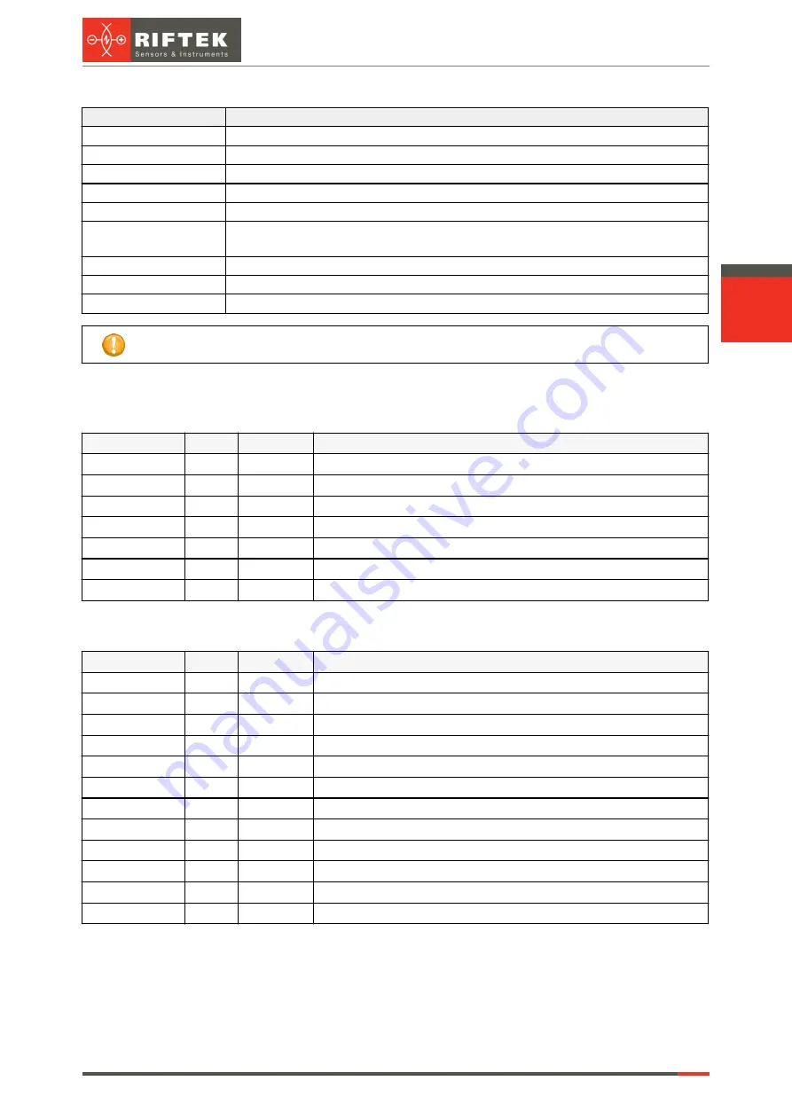
Parameters and buttons:
Parameter
Description
Sensor s/n
Serial number of the scanner.
Sensor target port
UDP port to which the scanner sends profiles (6003 by default).
Protocol
Protocol selection.
Server address
IP address of the robot.
Server port
Robot port (502 by default).
Debug log
Save the debug log: time and type of request from the robot, bytes of commands,
the response time of the program, response bytes, error text.
LOCK SENSOR
Lock the scanner to the protocol settings.
Force template change Forced template change for every received packet.
State
Enable the selected protocol.
When the
State
option is enabled, you cannot change parameters in the
PROTOCOLS
tab.
15.6.4.2. Packets and parameters
Send packet 1 with delay (ms).
Displacement
Length
Field
Description
0
2
TrID1
Transaction ID (set by the client, copied by the server in response)
2
2
ProtoID
Protocol type (0 = Modbus)
4
2
Len1
Quantity of following bytes
6
1
UnitID
Slave address
7
1
Fn1
Function number = 4
8
2
Adr1
Starting register address
10
2
Cnt1
Quantity of registers
Wait for the response, check the high-order bit of the 36th byte: 1 - perform
calculations, 0 - send zeroes in response. Send packet 2 (with results).
Displacement
Length
Field
Description
0
2
TrID1
Transaction ID (set by the client, copied by the server in response)
2
2
ProtoID
Protocol type (0 = Modbus)
4
2
Len1
Quantity of following bytes
6
1
UnitID
Slave address
7
1
Fn2
Function number = 16
8
2
Adr2
Starting register address
10
2
Cnt2
Quantity of registers
12
1
BCnt2
Byte counter
13
2
REG[1]
1st register
15
2
REG[2]
2nd register
...
...
...
...
13+2*(Cnt2-1)
2
REG[Cnt2] The last register
15.6.4.3. Types of calculations (commands) and assignment of registers
Data transmission from the scanner to the robot
:
13-16 bytes - the 1st control point, coordinate X
17-20 bytes - the 1st control point, coordinate Z
21-24 bytes - the 2nd control point, coordinate X

