296
Manual – IPOSplus®
22
Analog inputs/outputs
Assembler – Programming
22.3 Analog inputs/outputs
The analog inputs are differential inputs. The inputs/outputs can be used optionally as
either voltage or current inputs/outputs.
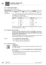
Assignment of value range / variable value for analog outputs is only valid if the scaling
factor of the parameter P110 is set to 1.
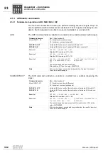
22.3.1 Reading analog inputs/outputs
The status of the analog inputs/outputs of the basic unit and the DIO11 terminal expan-
sion board can be written to variables of your choice using the
GETSYS
command. First
enter the variable into the GETSYS command, followed by the system value (here:
AN-
ALOG INPUTS
or
ANALOG OUTPUTS
).
The first input/output is written to the variable entered in the GETSYS command (Hxxx)
whilst the second is written to the subsequent variable (Hxxx + 1).
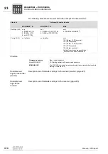
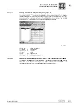
Example
Command
GETSYS H310 = ANALOG INPUTS
H310 contains the value of the analog input AI1
H311 contains the value of the analog input AI2
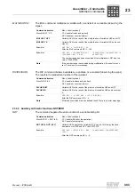
22.3.2 Setting analog outputs
The analog outputs are set using the
H479 (ANA.OUT IP)
and
H478 (ANA.OUT IP2)
system variables.
Command
SET H479 = K
(K = any constant within the aforementioned value range)
SET H479 describes analog output 1
SET H478 describes analog output 2
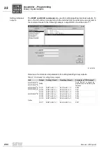
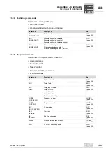
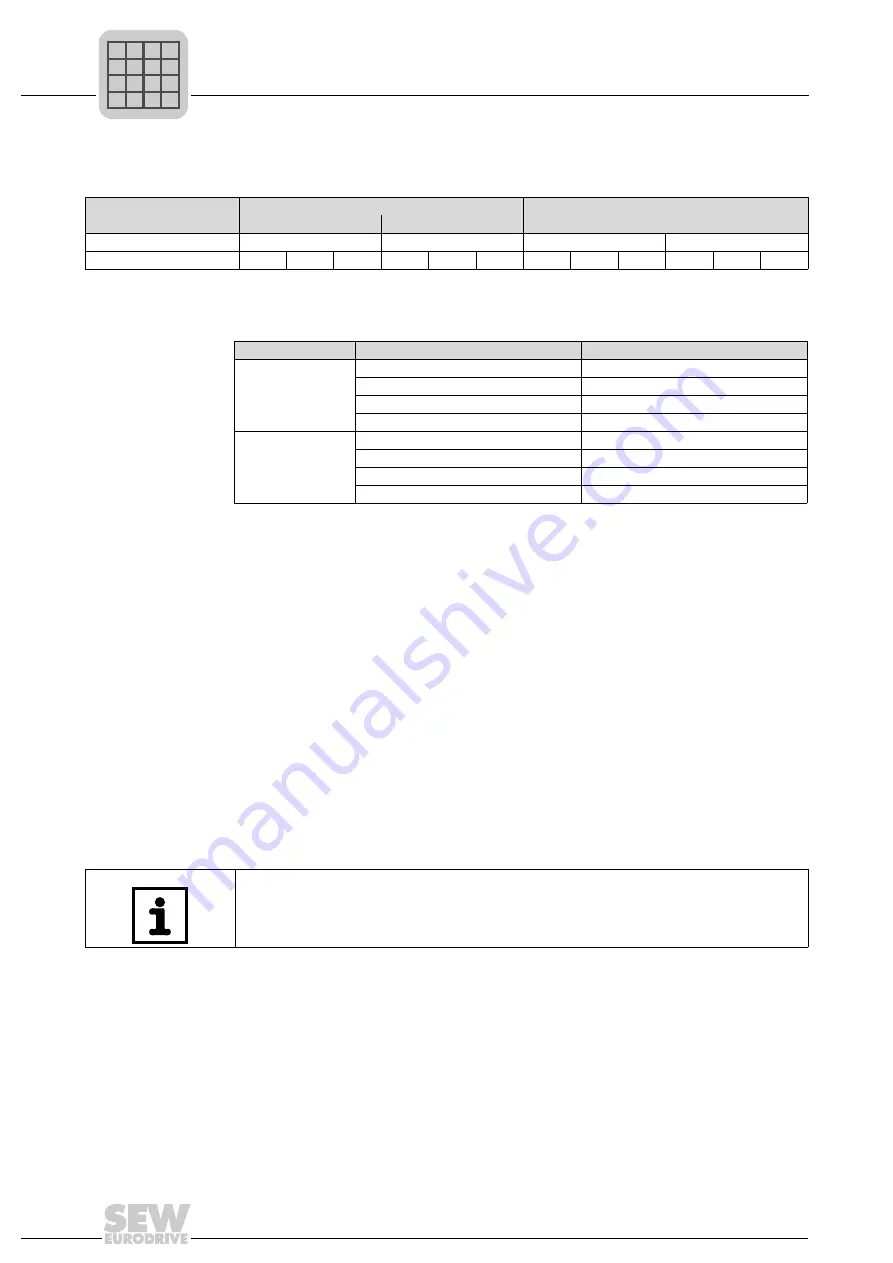
Table 6: Overview of the analog inputs/outputs
Analog inputs/outputs
Inputs
Outputs
Basic unit
Option
DIO11 option
Input/output
AI1
AI2
AO1
AO2
Terminal designation
AI11
AI12
AGND
AI21
AI22
AGND
AOV1
AOC1
AGND
AOV2
AOC2
AGND
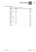
Table 7: Assigning value ranges to variable values
Input/output
Value range
Variable value
Output
- 10 ... 0 ... + 10 V
- 10 000 ... 0 ... + 10 000
0 ... + 10 V
0 ... + 10 000
0 ... + 20 mA
0 ... + 10 000
4 ... + 20 mA
0 ... + 10 000
Input
- 10 ... 0 ... + 10 V
- 10 000 ... 0 ... + 10 000
0 ... + 10 V
0 ... + 10 000
0 ... + 20 mA
0 ... + 5 000
4 ... + 20 mA
1000 ... + 5 000
INFORMATION
Prerequisite for setting: The corresponding analog output (P640 and P643) must be
set to "IPOS OUTPUT".
P
i
f
kVA
Hz
n
P
i
f
kVA
Hz
n

