80
Manual – IPOSplus®
6
Modulo function
Position Detection and Positioning
6.7.4
Project planning
6.7.5
Project planning examples
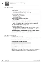
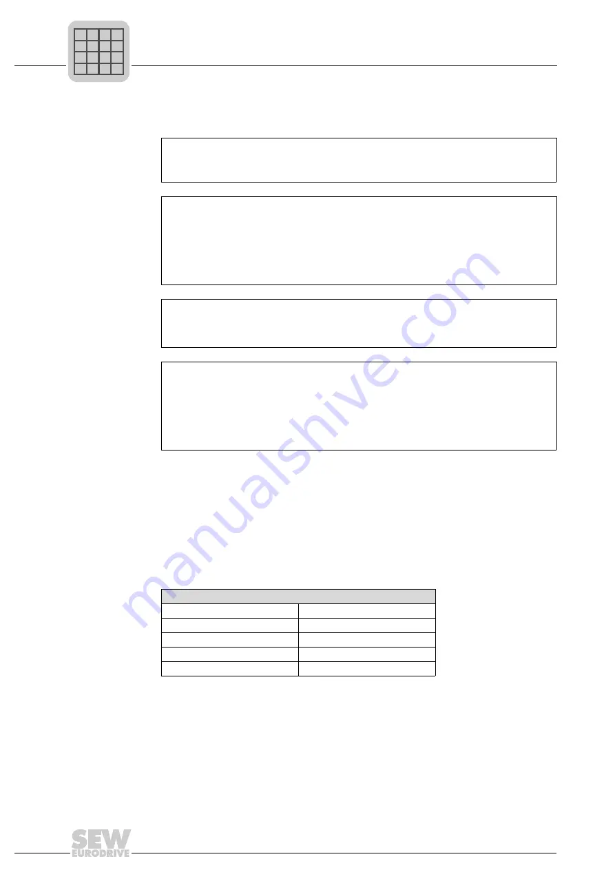
Chain conveyor
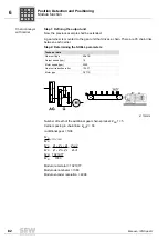
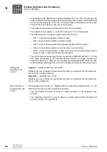
Step 1: Defining the output unit
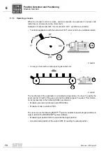
The positions for a chain conveyor are specified in output units. A 360° rotation at the
gear unit output corresponds to the modulo output unit of 360°.
Step 2: Determining the SHELL parameters
SEW employees can read off the number of teeth in the gear unit from the SEW Tech-
nical Manual (DriveNet) or from the electronic nameplate (only for Hiperface
®
).
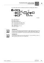
Definition of drive unit
•
Gear unit and the additional gear make up the output unit 360°
•
Determine the maximum target position in "Number of drive units"
•
Determine 16 bit or resolution (encoder x modulo numerator) for 360°
↓
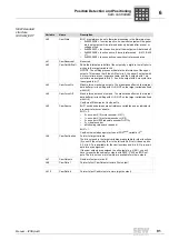
Determining the SHELL modulo parameters
•
Modulo function P960 (select travel strategy)
•
Modulo numerator P961
•
Modulo denominator P962
•
Modulo encoder resolution P963
Resources for determining the number of teeth in the gear unit:
•
SEW Technical Manual
•
SEW Wingear program to reduce the numerator/denominator factors
↓
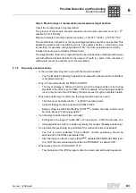
Modulo range of representation and maximum output position
•
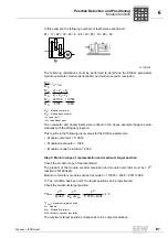
Condition for the range of representation: Modulo encoder resolution x modulo numerator < 2
31
•
Condition for maximum output position: = 2
31
/ (modulo encoder resolution × modulo numerator)
If this condition is not met, it can lead to positioning errors!
↓
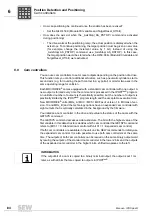
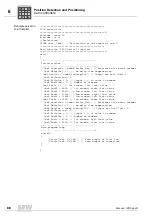
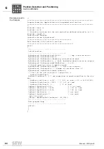
Realization in the IPOS
plus
®
program
•
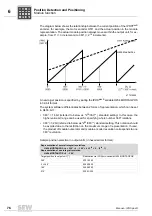
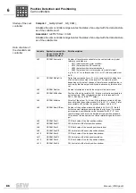
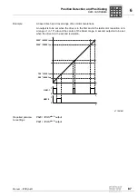
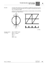
Specify setpoint position with the H454 ModTagPos variable: MOD.TAGPOS = k × 360° + 0 ... 360° = k
× 2
16
+ 0 ... (2
16
- 1)
•
Read off the actual position in the H455 ModActPos variable: MOD.ACTPOS = ... + 0 ... 360° = ... + 0
... (2
16
- 1)
The system software reads the target position specified in ModActPos and then sets the high word
to 0.
The actual position ModuloActPos always moves between 0° and 360°!
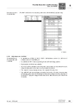
Technical data
Gear unit type
KA47B
Output speed [rpm]
19
Motor speed [rpm]
2000
Gear unit reduction ratio i
104.37
Motor type
DY71S
P
i
f
kVA
Hz
n
P
i
f
kVA
Hz
n

