•
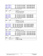
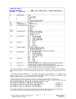
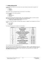
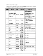
P1/2_PHYADDRESS
4..0
Port1 = 00000b; Port2 = 00001b
•
P1/2_PHYMODE
2..0
see
PHY_CONFIG
in the SYSTEM-CONTROL register area
•
P1/2_MIIMODE
1..0
MII-Interface (permanently set)
•
P1/2_SMIISOURCESYNC
Normal SMII-Mode
•
P1/2_FXMODE
see
PHY_CONFIG
in the SYSTEM-CONTROL register area
•
P1/2_AUTOMIDIXEN
see
PHY_CONFIG
in the SYSTEM-CONTROL register area
•
P1/2_NPMSGCODE
2..0
000b
•
P1/2_PHYENABLE
see
PHY_CONFIG
in the SYSTEM-CONTROL register area
•
REG2OUIIN
15..0
Default Value for SMII-Register2 (0x0033)
(1)
•
REG3OUIIN
15..0
Default Value for SMII-Register3 (0x2001)
(1)
(1)
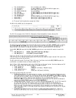
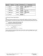
The values for both registers are composed as follows:
The NEC-OUI is 0x003013 and is interpreted as
1 2 3 4
...............
2
3
2
4
Bit
0 0 0 3 3 1
Hex
format
0 0 0 0 0 0 0
0 0 0 0 0
1
1
0
0
1
1
0
0
1
0
0
0 OUI
format
The PHY-ID is composed of the OUI [24:3] + Manufacturer Model Number[5:0] + Revision Number[3:0]
0 0 0 0 0 0 0 0 0 0 1 1 0 0 1 1 0 0 1 0 0 0
OUI[24:3]
Manufacturer Model Number[5:0]
0 0 0 0 0 0
Revision Number[3:0]
0 0
0
1
0 0 3 3 2 0 0 1
REG2OUIIN
REG3OUIIN
The parameters mentioned above for the internal Config port can be changed in the
PHY_CONFIG
register. In addition,
the
P1_PHY_ENB /P2_PHY_ENB
bits are also activated in this register. The parameters and the enable bit can be
transferred with a write access, as the required setup time of 200 ns is ensured by the ERTEC 200 hardware.
With the
PHY_RES_SEL
select bit in the
PHY_CONFIG
register, the user can select which reset pin is used for the
PHYs:
•
PHY_RES_SEL = 0
RESET_N from ERTEC 200 Power-ON-Reset
•
PHY_RES_SEL = 1
PHY_RESET_N from IRT-Switch
If the Power-ON-reset is used, then the PHYs are active after the RESET phase.
If the PHY_Reset_N is used, and the SMI module in the IRT switch has not been activated, then the PHYs remain in the
reset state (no power loss from the PHYs).
The HW reset must be present for at least 100µs. In the case of a software reset via the
PHY_CONFIG
register, the
reset duration is increased internally to 256µs to stabilize the PLL.
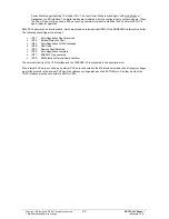
Each PHY has 6 LED outputs that are routed to the GPIOs[7:0] as an alternative function. Four status displays per PHY
can be wired to external LEDs. The following displays are available in parallel:
•
P1/P2_DUPLEX_N
(Half/Full)
•
P1/P2_SPEED_N
(100BASE-TX/FX Status, 10BASE-T Status)
•
P1/P2_LINK_STATUS_N
(On/Off)
•
P1/P2_ACTIVITY_N
(No/Receive, No/Transmit, No/Activity)
Power management functionality of the PHYs:
•
Hardware-Power-Down:
This state is attained via hardware reset. The PHY is switched off, limiting the power
loss to approximately 0 mW per PHY. This state is exited when bit
P1_PHY_ENB /P2_PHY_ENB=1
. All analog
and digital modes are initialized, and the configuration is stored. After this, the PHY register set can be assigned
parameters for the first time. Internally, a reset extension of 5.2 ms is initiated in the PHY with
P1/P2_PHY_ENB=1
to stabilize the PLL and all analog and digital components. The operational readiness is
displayed in the
PHY_STATUS
register with bit
P1/P2_PWRUPRST=1
.
•
Software-Power-Down:
Activated via the PHY register 0 Basic-Control-Register Bit11. The PHY then goes into
the LOW-Power-State. The MDIO interface continues to be active. Activities on the MII interface are
suppressed. The power loss in Low-Power-State is approximately 15 mW per PHY. After the Power-Down
Mode is complete, the digital modules are reinitialized, but the configuration is not saved again. When the
Power Down state is exited, a 256-µs reset is generated internally to stabilize the PLL before the PHY is again
ready for operation.
•
Automatic-Power-Down:
Set via the PHY register 17 ModeControl/ Status Register Bit 13. If there is no
activity on the MII interface, then the Power Down mode is automatically entered. The power loss in Low-
Copyright © Siemens AG 2007. All rights reserved.
89
ERTEC 200 Manual
Technical data subject to change
Version 1.1.0


