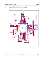
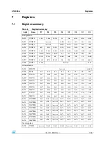
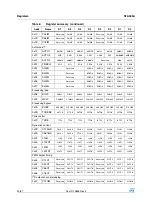
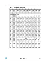

Registers
STA309A
24/67
Doc ID 13855 Rev 4
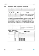
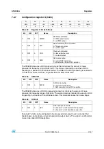
7.2.2 Configuration
register
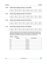
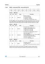
B (0x01) - serial input formats
Serial data interface
The STA309A audio serial input interfaces with standard digital audio components and
accepts a number of serial data formats. STA309A always acts a slave when receiving audio
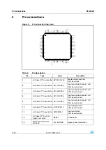
input from standard digital audio components. Serial data for eight channels is provided
using 6 input pins: left/right clock LRCKI (pin 10), serial clock BICKI (pin 11), serial data 1
and 2 SDI12 (pin 9), serial data 3 and 4 SDI34 (pin 8), serial data 5 and 6 SDI56 (pin 7), and
serial data 7 and 8 SDI78 (pin 6). The SAI/SAIFB register (Configuration Register B,
address 0x01) is used to specify the serial data format. The default serial data format is I
2
S,
MSB-first. Available formats are shown in the tables and figure that follow.
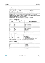
Note:
Serial input and output formats are specified separately
For example, SAI = 1110 and SAIFB = 1 would specify right-justified 16-bit data, LSB-first.
D7
D6
D5
D4
D3
D2
D1
D0
Reserved
SAIFB
SAI3
SAI2
SAI1
SAI0
0
0
0
0
0
0
0
0
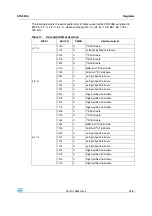
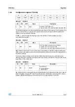
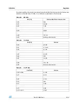
Table 15.
SAI bits
Bit
RW
RST
Name
Description
0
RW
0
SAI0
Serial audio input interface format: determines the
interface format of the input serial digital audio
interface.
1
RW
0
SAI1
2
RW
0
SAI2
3
RW
0
SAI3
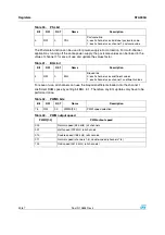
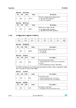
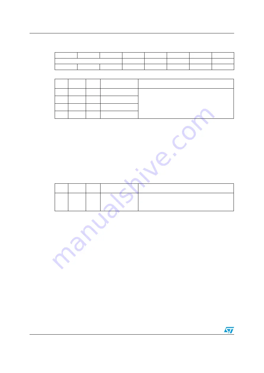
Table 16.
SAIFB bit
Bit
RW
RST
Name
Description
4
RW
0
SAIFB
Determines MSB or LSB first for all SAO formats:
0: MSB first
1: LSB first


