57
Control Registers
3
Powerup/Reset Default = $0000
Target Calibration Voltage HI and Lo Registers’ Bit Definitions
Bits 15 through 00:
TVH & TVL [15...0] -
The user writes a digital value to this
register which represents the expected result for the calibration
voltage connected to the inputs. The digital value must be in
two’s complement format. Below is an example explaining the
use of this register.
Example:
Input +2.25 V for calibration on the
±
5 V scale. The
32-bit code for the expected value can be determined by the
following equation:
E
in
= E
fsr
x N
adc
/2
32
where: E
in
= Input voltage
E
lo
= Lower end of Input Range
E
fsr
= Full-scale Input Range
N
adc
= A/D Converter reading
Solving for N
adc
yields:
N
adc
= E
in
* 2
32
For the above example, N
adc
=
$3999 9999
. This number is in
two’s complement format and would be entered in the TCV
register as:
Target Calibration Voltage HI =
$3999
Target Calibration Voltage LO =
$9999
NOTE:
Due to the way the DSP handles calibration, unipolar ranges must use E
FSR
of
their bipolar range. For example, a unipolar range of 0 to 10 V uses a E
FSR
of ±10 V (20 V)
in the aforementioned equation.
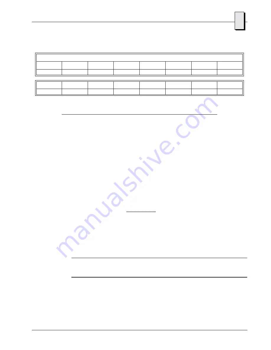
Table 3-10 Target Calibration Voltage Register LO’s Bit Map
Target Calibration Voltage Register LO (Offset $000C) Read/Write, Byte/Word
Bit 15
Bit 14
Bit 13
Bit 12
Bit 11
Bit 10
Bit 09
Bit 08
TVL15
TVL14
TVL13
TVL12
TVL11
TVL10
TVL9
TVL8
Bit 07
Bit 06
Bit 05
Bit 04
Bit 03
Bit 02
Bit 01
Bit 00
TVL7
TVL6
TVL5
TVL4
TVL3
TVL2
TVL1
TVL0
E
fsr
Artisan Technology Group - Quality Instrumentation ... Guaranteed | (888) 88-SOURCE | www.artisantg.com


