9-1
Section 9. Input / Output Instructions
Input/Output Instructions are used to make measurements on sensor signals and to set or
read digital control ports. They are also used to control SDM peripherals and for tasks such
as internal calibration. These instructions write data to (or read data from) Input Storage
memory locations.
Table 9-1 lists the voltage measurement range codes for all instructions which make
analogue voltage measurements.
Table 9-1 Input Voltage Ranges and Codes
Range Code
Full Scale Range
Resolution
1
Slow
Fast
60Hz
50Hz
(mV)
(
µ
V)
2.72ms
250
µ
s
Reject.
Reject.
Integ.
2
Integ.
3
0
10
20
30
autorange
1
11
21
31
±2.5
0.33
2
12
22
32
±7.5
1.
3
13
23
33
±25
3.33
4
14
24
34
±250
33.3
5
15
25
35
±2500
333.
1
Differential measurement; resolution for single-ended measurement is twice
value shown.
2
272
µ
s on ±2500mV range.
3
25
µ
s on ±2500mV range.
When a voltage input exceeds the range programmed, the value
which is stored is set to the maximum negative number and
displayed as -99999 in high resolution or -6999 in low resolution.
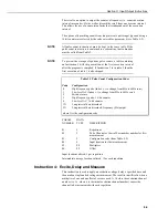
Instruction 1: Single-Ended Volts
This instruction is used to measure the voltage at a single-ended input with respect
to ground. The output is in millivolts.
PARAM.
DATA
NUMBER
TYPE
DESCRIPTION
01:
2
Repetitions
02:
2
Range code (Table 9-1)
03:
2
Channel number for first measurement
04:
4
input location for first measurement
05:
FP
Multiplier
06:
FP
Offset
Input locations altered:
1 per repetition
Instruction 2: Differential Volts
This instruction measures the voltage difference between the high and low inputs
of a differential channel. Table 9-1 contains all valid voltage ranges and their
codes. Both the high and low inputs must be within ±2.5V of the CR10X’s ground
(see description of Common Mode Range in Section 14). Pyranometer and
NOTE


