Part 1. Overview
OV-19
The CR10X is now programmed to measure the internal temperature every five
seconds and send each reading to Final Storage. Values in Final Storage can be
viewed using the *7 Mode.
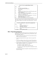
Press these
Display will show
Explanation of this
keys:
(ID: Data):
step:
*7
07: 13.000
Enter *7 Mode. The Display Storage Pointer
(DSP) is at location 13 (in this example).
A
01: 0102
Advance to the first value, the Output Array
ID. 102 indicates the Output Flag was set by
the second instruction in Program Table 1.
A
02: 21.23
Advance to the first stored temperature.
A
01: 0102
Advance to the next output array. Same
Output Array ID.
A
02: 21.42
Advance to 2nd stored temp, 21.42 deg. C.
Notice that there are no date and time tags on the data. These can be obtained by
using Instruction 77, as shown in the next example.
If a terminal is used to communicate with the CR10X, telecommunications com-
mands (see Section 5) can be used to view all the elements of an Output Array (in
this case the ID and temperature) at the same time.
OV5.2 Sample Program 1 (Using Edlog)
Edlog provides a useful and convenient way to write your datalogger programs on
a PC off-line. Programs can be compiled and checked before downloading to the
datalogger.
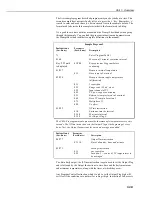
The following shows the same basic program example used in the previous
section as it would be programmed using Edlog:
*Table 1 Program
01:
5.0
Execution Interval (seconds)
1: Internal Temperature (P17)
1:
1
Loc [ CR10XTemp ]
2: Do (P86)
1:
10
Set Output Flag High
3:Sample (P70)
1:
1
Reps
2:
1
Loc[ CR10XTemp ]
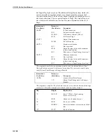
The program can also be created using Short Cut – see the PC200 User Guide.
OV5.3 Sample Program 2 (Direct Programming)
This second example is more representative of a real-life data collection situation.
Once again the internal temperature is measured, but this time it is used as a
reference temperature for the differential voltage measurement of a type T
(copper-constantan) thermocouple (new CR10Xs are delivered with a short type T
thermocouple connected to differential channel 5).


