CR10X User Guide
3-2
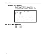
3.3 Entering Negative Numbers
After entering a number, press ‘-’ (if using a computer) or
C
to change the num-
ber’s sign. On floating point numbers a minus sign (-) will appear to the left of the
number. Excitation voltages in millivolts for I/O Instructions are 4-digit integers;
when
C
is pressed two minus signs (--) will appear to the right of the number
indicating a negative excitation. Even though this display is the same as that
indicating an indexed input location, there is no indexing effect on the excitation
voltage.
3.4 Indexing Input Locations and Control Ports
When used within a loop, the parameter for input locations and the commands to
set, toggle or pulse a port can be indexed to the loop counter. The loop counter is
added to the indexed value to determine the actual input location or port the in-
struction acts on. Normally the loop counter is incremented by 1 after each pass
through the loop. Instruction 90, Step Loop Index, allows the increment step to be
changed. See Instructions 87 and 90, Section 12, for more details.
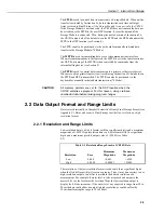
To index an input location (4-digit integer) or Set Port command (2-digit integer)
parameter, press
C
or ‘-’ after entering the value but before pressing
A
to enter the
parameter. Two minus signs (--) will be displayed to the right of the parameter.
3.5 Voltage Range and Overrange Detection
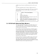
The voltage range code parameter in Input/Output Instructions is used to specify
the full scale range of the measurement and the integration period for the meas-
urement (see Table 3-1).
Table 3-1 Input Voltage Ranges and Codes
Range Code
Full Scale Range
Resolution
1
Slow
Fast
60Hz
50Hz
(mV)
(
µ
V)
2.72ms
250
µ
s
Reject.
Reject.
Integ.
2
Integ.
3
1
11
21
31
±2.5
0.33
2
12
22
32
±7.5
1.
3
13
23
33
±25
3.33
4
14
24
34
±250
33.3
5
15
25
35
±2500
333.
1
Differential measurement; resolution for single-ended measurement is twice
value shown.
2
272
µ
s on ±2500mV range.
3
25
µ
s on ±2500mV range.
The full scale range selected should be the smallest that will accommodate the full
scale output of the sensor being monitored. Using the smallest possible range
results in the best resolution for the measurement.
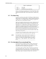
Four different integration sequences are possible. The relative immunity of the
integration sequences to random noise is:
1.
50Hz rejection = 60Hz rejection
2.
2.72ms integration
3.
250
µ
s integration.
The 50Hz rejection integration rejects noise from 50Hz AC line power.


