11-1
Section 11. Output Processing
Instructions
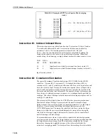
Instruction 69: Wind Vector
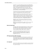
Instruction 69 processes the primary variables of wind speed and direction from
either polar (wind speed and direction) or orthogonal (fixed East and North
propellers) sensors. It uses the raw data to generate the mean wind speed, the
mean wind vector magnitude and the mean wind vector direction over an output
interval. Two different calculations of wind vector direction (and standard devia-
tion of wind vector direction) are available, one of which is weighted for wind
speed.
When used with polar sensors, the instruction does a modulo divide by 360 on
wind direction, which allows the wind direction (in degrees) to be 0 to 360, 0 to
540, less than 0, or greater than 540. The ability to handle a negative reading is
useful in an example where a difficult to reach wind vane is improperly oriented
and outputs 0 degrees at a true reading of 340 degrees, for example. The simplest
solution is to enter an offset of -20 in the instruction monitoring the wind vane,
which results in 0 to 360 degrees following the modulo divide.
When a wind speed sample is 0, the sample is not used in the computation of wind
direction. At low wind speeds, when the wind direction readings may be
erroneous, you may not want a sample less than the sensor threshold used in the
calculation of mean unit vector direction, mean resultant wind direction or
resultant wind speed. If this is the case, Instruction 89 can be used to check the
wind speed, and if less than the threshold, Instruction 30 can set the wind speed
location(s) equal to 0.
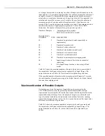
Standard deviation can be processed in one of two ways: 1) using every sample
taken during the output period, or, 2) by averaging standard deviations processed
from shorter sub-intervals of the output period. Averaging sub-interval standard
deviations minimises the effects of meander under light wind conditions and
provides more complete information for periods of transition
1
.
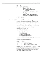
The standard deviation of horizontal wind fluctuations from sub-intervals is cal-
culated as follows:
σ
(
Θ
)=[(N
1
(
σΘ
1
)
2
+N
2
(
σΘ
2
)
2
...+N
m
(
σΘ
m
)
2
)/N]
1/2
where
σ
(
Θ
) is the standard deviation over the output interval,
σΘ
1
...
σΘ
m
are
sub-interval standard deviations, N
1
...
N
m
are the numbers of samples (with
windspeed >0) in each sub-interval, and N is the total number of samples.
The algorithm treats periods of zero wind speed as periods of zero
variation in wind direction.
1
EPA On-site Meteorological Program Guidance for Regulatory Modeling Applications.
NOTE


