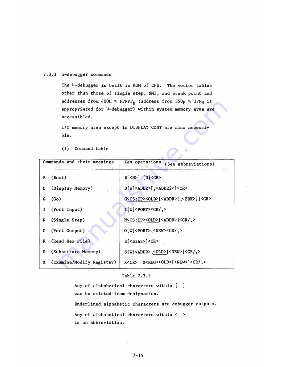
7.3.3 ^-debugger commands
The ^-debugger is built in ROM of CPU. The vector tables
other than those of single step, NMI, and break point and
addresses from 400H ^ FFFFF
jj
(address from 350^
*\
j
3FFfl is
appropriated for ^-debugger) within system memory area are
accessibled.
I/O memory area except in DISPLAY CONT are also accessi
ble.
(1) Command table
Commands and their meanings
Key operations (See abbreviations)
B (Boot)
b
[<
n
>] [
d
]<
c r
>
D (Display Memory)
D[W]<ADDR>[,<ADDR2>]<CR>
G (Go)
G<CS:IP><OLD>[<ADDR>[,<BRK>]]<CR>
1 (Port Input)
I[W]<P0RT><CR/,>
N (Single Step)
N<CS:IP><0LD>[<ADDR>]<CR/,>
0 (Port Output)
0[W]<P0RT>,<NEW><CR/,>
R (Read Hex File)
R[<BIAS>]<CR>
S (Substitute Memory)
S[W]<ADDR>,<OLD>t<NEW>]<CR/,>
X (Examine/Modify Register)
X<CR> X<REG><OLD>[<NEW>]<CR/,>
Table 7.3.5
Any of alphabetical characters within [ ]
can be omitted from designation.
Underlined alphabetic characters are debugger outputs.
Any of alphabetical characters within < >
is an abbreviation.
7-14
Summary of Contents for AS-100M
Page 1: ...Canon FIELD SERVICE MANUAL ...
Page 26: ...2 2 5 FDD Media Canon specified MDD 512DD 512B sector 2 3 ...
Page 30: ...ICURRENT LÖÖPl Available soon 2 7 ...
Page 39: ...3 3 5 FDD 3 3 1 External View Housing plate Fig 3 3 1 Fig 3 3 2 3 5 ...
Page 41: ...3 4 8 FDD 3 4 1 External View Housing Fig 3 4 1 Fig 3 4 2 3 7 ...
Page 43: ...3 5 PRINTER Refer to PRINTER TECHNICAL GUIDE 3 9 ...
Page 47: ... 2 KEYBOARD 3 5 FDD 4 3 ...
Page 48: ... 8 FDD 4 4 ...
Page 100: ...8 FDD Fuse 1 Replace two 5A fuses 8 FDD as In Fig 5 5 7 5 23 ...
Page 107: ...Chapter 7 Troubleshooting 7 1 At System Up 7 1 ...
Page 129: ...Chapter 8 Appendix 8 1 Unit Configuration and General Wiring ...
Page 130: ...8 1 Unit Configurations and General Wiring 8 1 POWER SWITCH ...
Page 135: ...Fig 8 1 6 8 FDD For 115 120 230 240V POWER SWITCH ...
Page 136: ...CANON INC COPYRIGHT g 198 BY CANON INC Printed in Japan Feb 1983 E Y 8 6 0 7 2 2 2 2 ...


