CDE360 Vector Control AC Drive Chapter 6 Parameters Description
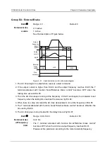
Choose any of the following two connection mode for interlock circuit:
1
)
A contact of the manual on/off switch of each motor is wired to the interlock circuit. The
logic will detect if a motor is unavailable and start the next available motor instead.
2
)
A contact of thermal relay (or other protective device) of each motor is wired to the
interlock circuit. The logic will detect if a motor has fault and decide to stop it.
Examples of motor interlock in multi-pump control logic:
Suppose the motor startup sequence is: 1 -> 2 -> 3 -> 4.
If motor 3 is removed,then the motor startup sequence is: 1 -> 2 -> 4.
Then if motor 3 is added again,it will be added to the last of startup sequence: 1 -> 2 -> 4
-> 3.
If the multi-pump control system stops,or enters into sleep mode,the motor startup
sequence will return to the initial status when system runs again: 1 -> 2 -> 3 -> 4.
E6.06
Range: 0000~1111
Default: 0000
Digital setting of
Motor interlock
0: Not connected to multi-pump system
1: Connected to multi-pump system
Unit's digit: Motor1#
Ten's digit: Motor2#
Hundred's digit: Motor3#
Thousand's digit: Motor4#
E6.07
Range: 0.1~6000.0
Default: 48.0
Auto-change
interval
Unit: h
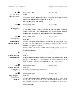
When the lasting time exceeds the set value of E6.07,AC drive will begin
auto changing if idle motor numbers is no less than E6.09 and
speed-regulated motor operation frequency is lower than E6.08.
Auto change function is to make an average distribution of the total
working time to each motor in multi-pump system.
E6.08
Range: 0.00~
b0.00
Default: 45.00
Auto-change
frequency limit
Unit: Hz
Auto-change function will be forbidden when AC drive output higher than
the frequency E6.08 set.
E6.09
Range: 1~3
Default: 1
Auto-change
Motor limit
See the parameter description of
E6.07
.
E6.10
Range: 0.00~
b0.00
Default: 48.00
Add pump
frequency 1
Unit: Hz
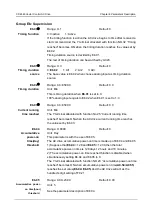
The frequency to add the first auxiliary pump(controlled via a Y/T terminal
with No.41 function “Motor 2# Control output”).


