background image

Appendix E: Three Letter Commands 


  113 


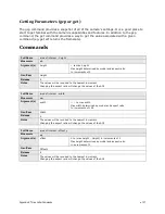
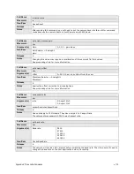
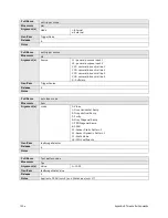
Full Name  

put camera in genicam mode


Mnemonic  

gen  


Release 

Notes  

The camera returns an OK> prompt then switches into GenICam mode.  


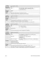
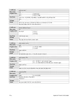
Full Name  

get values


Mnemonic  

get


Argument(s)  

command  

String containing a command with a value associated with it(e.g. 

ssf

ffm

, etc.) 

Release 

Notes  

The command does not return the units(e.g. 

ssf

 returns 

30

 without the Hz) 


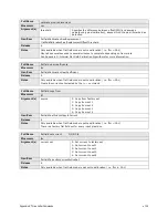
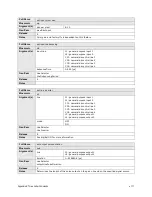
Full Name  

get line status


Mnemonic  

gls


Argument(s)  

line 

L1: get status of general purpose input 1(line1) 
L2: get status of general purpose input 2(line2) 
CC1: get status of camera control line 1(CC1) 
CC2: get status of camera control line 2(CC2) 
CC3: get status of camera control line 3(CC3) 
CC4: get status of camera control line 4(CC4) 
L3: get status of general purpose output 1(line3) 
L4: get status of general purpose output 2(line4)


GenICam  

LineSelector 
LineStatus


Release 

Notes  

Returns 1 for high and 0 for low 


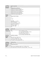
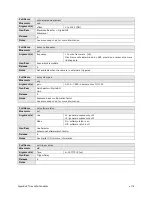
Full Name  

help


Mnemonic  

h


Release 

Notes  

Lists all of the camera’s command. Commands that are not available due the camera’s current 

settings have the text 

Not Available 

after the description. 


Summary of Contents for FA-80-12M1H-XX-R

Page 1: ...Falcon2 Camera User s Manual 4M 8M and 12M Area Imaging P N 03 032 20107 04 www teledynedalsa com ...

Page 2: ...edyne DALSA Teledyne DALSA is headquartered in Waterloo Ontario Canada We have sales offices in the USA Europe and Asia plus a worldwide network of representatives and agents to serve you efficiently Contact information for sales and support inquiries plus links to maps and directions to our offices can be found here Sales Offices http www teledynedalsa com corp contact offices Technical Support h...

Page 3: ...up______________________________________________________________________________ 18 Minimum Recommended System Requirements 18 Setup Steps Overview 18 1 Install and Configure Frame Grabber and Software including GUI 18 2 Connect Camera Link Cables and Power 18 3 Establish communicating with the camera 18 4 Check camera LED settings and test pattern 18 5 Operate the Camera 18 Step 1 Install and con...

Page 4: ...etection Overview 66 How to do an FFC Setup in the Camera 68 How to do a FFC Setup via Sapera CamExpert 70 Defective Pixel Detection and Replacement 75 Image Format Controls Category 77 Test Patterns 81 Multiple AOI Mode 84 Camera Link Transport Layer Category 85 Camera Link Transport Layer Feature Description 86 Serial Port Control Category 89 Feature Description 89 Automatic Serial Speed Detecti...

Page 5: ..._________________ 105 Putting Camera in TLC Mode 105 Setting the Sapera s COM Port Mapping 106 Getting Started 106 The Help Command h or 106 Getting Parameters gcp or get 107 Commands 107 EMC Declaration of Conformity _____________________________________________________________________________ 122 Revision History____________________________________________________________________________________...

Page 6: ...loth To remove severe stains use a soft cloth dampened with a small quantity of neutral detergent and then wipe dry Do not use volatile solvents such as benzene and thinners as they can damage the surface finish Further cleaning instructions are below Though this camera supports hot plugging it is recommended that you power down and disconnect power to the camera before you add or replace system c...

Page 7: ... PRNU Pixel Response Non Uniformity levels In addition region of interest features create opportunities for higher frame rates and new applications The cameras are compliant with Camera Link specifications delivering 8 or 10 bits of data on 8 or 10 taps frame rates are specified at 8 bits Further the M42x1 thread opening allows the use of your lens of choice Key Features 12 8 and 4 mega pixels Sel...

Page 8: ...FA 80 8M100 XX R 8M pixel monochrome Camera Link FA 81 8M100 XX R 8M pixel color Camera Link FA 80 4M180 XX R 4M pixel monochrome Camera Link FA 81 4M180 XX R 4M pixel color Camera Link Table 2 Software Software Product Number Version Number Camera firmware Embedded within camera GenICam support XML camera description file Embedded within camera Recommended Sapera LT including CamExpert GUI applic...

Page 9: ...e temperature Connectors and Mechanicals Data Interface Full or Extended Camera Link 2 x SDR26 Power Connector Hirose 12 pin circular Power Supply 12 V to 24 V DC Power Dissipation 9 5 W typical Mini USB connector Future use Lens Mount M42 x 1 F mount optional Sensor Alignment 0 2º in X Y directions Size 60 mm H x 60 mm W x 80 5 mm D Mass 300 g Compliance Regulatory Compliance CE and RoHS Maximum ...

Page 10: ...m Column Maximum Rows Frame Rate 8 BPP Frame Rate 9 BPP Frame Rate 10 BPP 12M 4 3 4096 3072 58 58 58 8M 1 1 2816 2816 90 89 66 8M 4 3 3328 2502 86 86 74 4M 1 1 2048 2048 148 122 91 4M 4 3 2432 1728 168 145 108 Sensor bits per pixel An online frame rate calculator is available from the Falcon2 product page on the Teledyne DALSA site here Certifications Compliance EN 55011 CISPR 11 EN 55022 CISPR 22...

Page 11: ...ming Convention specification V1 5 This description takes the form of an XML device description file complying with the syntax defined by the GenApi module of the GenICam specification The camera uses the GenICam Generic Control Protocol GenCP V1 0 to communicate over the Camera Link serial port Additional information on GenICam can be found here www genicam org ...

Page 12: ...graph describes the camera s response to different wavelengths of light excluding lens and light source characteristics Figure 1 Falcon2 Monochrome 8M Spectral Responsivity Note 8 Taps 10 bits Camera Link FFC on 24 fps except 400 nm measured at 10 fps ND 0 3 filtered light ...

Page 13: ...on FFC on color corrected 4 fps except for color red which used different frame rate at wavelength 560nm and below 400 480nm was done at 1 8 fps 500 nm was done at 4 fps and 520 560 BG 38 filtered light 0 5 10 15 20 25 30 400 440 480 520 560 600 640 680 720 760 800 840 880 Responsivity DN nJ cm 2 Wavelength nm Red GreenRed GreenBlue Blue ...

Page 14: ...14 The Falcon2 Cameras Figure 3 Quantum Efficiency INSERT QE GRAPH HERE ...

Page 15: ...Count 7 Based on estimation algorithm Detection Threshold Groups of dark and light pixels Combined dark and light pixel defects Tolerated Count 0 Glass Spot Defect Definition defects kernel 8 3x3 8 3x3 Illuminated with aperture collimated light source Detection Threshold of avage 8 4 frame average any pixel outside 8 of average Tolerated Count 1 1 spot of 9 pixels allowed No limit on spots below 9...

Page 16: ...ooking at the front of the camera without a lens The Teledyne DALSA logo on the side of the case will be right side up The monochrome camera uses the same layout but without the color filters The color camera model has a Bayer filter applied to the CMOS sensor to allow for color separation Each individual pixel is covered by either a red green or blue filter as shown in the figure above The camera...

Page 17: ...The Falcon2 Cameras 17 Mechanicals Figure 5 Camera Mechanical ADD MECHANICAL PDF HERE ...

Page 18: ... is embedded within the Falcon2 firmware allowing GenCP compliant applications to know the camera s capabilities immediately after connection Installing SaperaLT gives you access to the CamExpert GUI a GenCP compliant application The SaperaLT software is available from the Falcon2 page of the Teledyne DALSA Web site here 2 Connect Camera Link Cables and Power Connect the Camera Link cables from th...

Page 19: ... the camera interfacing tool supported by the Sapera library and comes bundled with SaperaLT Using CamExpert is the simplest and quickest way to send commands to and receive information from the camera Camera link Environment These cameras implement the Camera link specification which defines the device capabilities The Camera link XML device description file is embedded within the camera firmware...

Page 20: ...quirement 12 VDC to 24 VDC 5 2 Amps Before connecting power to the camera test all power supplies Figure 7 12 pin Hirose Circular Male Power Plug Power Connector Table 6 Power Plug Pinout Pin Description Pin Description 1 GND 7 OUT2 2 12 V to 24 V DC 8 OUT2 3 OUT1 9 NC 4 OUT1 10 NC 5 IN1 Trigger 11 IN2 Trigger 6 IN1 Trigger 12 IN2 Trigger WARNING When setting up the camera s power supplies follow ...

Page 21: ...k The camera accepts control inputs through the mini Camera Link SDR 26F connector The camera ships factory setting in internal sync and internally triggered integration Frame Start Trigger EXSYNC The EXSYNC signal tells the camera when to integrate and readout the image It can be either an internally generated signal by the camera or it can be supplied externally via CC GPIO and software command ...

Page 22: ...amera Link compliant interface by double clicking the desktop icon created during the software installation 2 CamExpert will search for Sapera devices installed on your system In the Devices list area on the left side of the GUI the connected Falcon2 camera will be shown 3 Select the Falcon2 camera device by clicking on the camera s user defined name By default the camera is identified by its seri...

Page 23: ...23 Figure 8 Two CamExpert windows shown one connected to the frame grabber and one connected to the camera At this point you are ready to start operating the camera in order to acquire images set camera functions and save settings ...

Page 24: ...isible are usually for Teledyne DALSA or third party software usage and not typically required by end user applications Figure 9 Camera Information Category in CamExpert Camera Information Feature Descriptions The following table describes these parameters along with their view attribute and in which firmware version the feature was introduced Additionally the Name category indicates which paramet...

Page 25: ...alues Falcon2 Name DeviceVersion Display Name Device Version Name Space Standard Firmware Release 00 Visibility Beginner Access Read only Type String Values e g 255 90 259 Notes This is an automatically generated number that specifically identifies the software build Name DeviceFirmwareVersion Display Name Firmware Version Name Space Standard Firmware Release 00 Visibility Beginner Access Read onl...

Page 26: ...e g My Camera Notes This feature is automatically saved to the camera s non volatile memory when it is written Name UserSetDefaultSelector Display Name User Set Default Selector Power up Configuration Name Space Standard Firmware Release 00 Visibility Beginner Access Read Write Type Enumeration Values None no default set is loaded The camera uses model default values and no factory calibrated valu...

Page 27: ...Firmware Release 00 Visibility Beginner Access Read Write Type Command Notes Saves the camera configuration set specified by the User Set Selector feature to the camera Disabled when flatfieldCorrectionMode Calibration or UserSetSelector Factory Invisible Features Name deviceDFNCVersionMajor Display Name DFNC Major revision Name Space DFNC Firmware Release 00 Visibility Invisible Access Read only ...

Page 28: ...r Set 1 to 4 or the factory settings can be restored using the User Set Selector and User Set Load parameters Either the Factory or one of the User settings can be specified as the Default Set by selecting it in the User Set Default Selector The chosen set is automatically loaded when the camera is reset or powered up It should also be noted that the value of Default Selector will automatically ge...

Page 29: ... Validation is turned off in this mode so that the order in which the feature values are set is irrelevant For example if validation was on during this process AcquisitionFrameRate would have to be set before ExposureTime because the maximum ExposureTime can be limited by the camera s frame rate CamExpert uses feature streaming when saving or loading the camera s ccf file This file can be used to ...

Page 30: ...ird party SDK if it is not GenAPI 2 4 compliant Name DeviceRegistersPersistenceEnd Display Name Device Registers Persistence End Name Space SFNC Firmware Release 05 Visibility Invisible Access Read Write Type Command Notes Available and automatic with GenAPI 2 4 Called after a camera configuration feature save with third party SDK if it is not GenAPI 2 4 compliant Name DeviceRegistersCheck Display...

Page 31: ... end user applications Sensor Control Feature Descriptions The following table describes these parameters along with their view attribute and minimum camera firmware version required Additionally the firmware column will indicate which parameter is a member of the DALSA Features Naming Convention DFNC versus the GenICam Standard Features Naming Convention SFNC or a custom camera feature Name Devic...

Page 32: ...e maximum height in pixels of the AOI for the given aspect ratio sensorResolutionAspectRatio Name AcquisitionFrameRate Display Name Frame Rate Name Space Standard Firmware Release 00 Visibility Beginner Access Read Write Read only when TriggerMode equals On Type Float Units Hertz Values 1 to x Hz where x is a calculated maximum See Notes Notes Specifies the camera internal frame rate in Hz Note th...

Page 33: ...th overhead 8 bpp 50 bpp 30 10 bpp 30 External Trigger 20 µs to 1 second Notes Sets the exposure time in microseconds when the ExposureMode feature is set to Timed Name GainSelector Display Name Exposure Mode Name Space SFNC Firmware Release 00 Visibility Beginner Access Read Write Type Enumeration Values AnalogAll1 Apply fine gain adjustment to all analog taps AnalogAllRaw1 Same as AnalogAll1 exp...

Page 34: ...al channels or taps after flat field correction AnalogAll1 All analog channels Apply black level adjustment to all analog taps Notes Selects which black level i e dark offset is controlled when adjusting the black level feature Name BlackLevel Display Name Black Level Name Space SFNC Firmware Release 00 Visibility Beginner Access Read Write Read only when TriggerMode equals On Type Integer Values ...

Page 35: ...ype Integer Values 0 65535 Notes This feature should only be used by experts and is normally set to the factory calibrated default Changing this value may result in unexpected image artefacts Name sensorExposureControlMode Display Name Exposure Control Mode Name Space Custom Firmware Release 05 Visibility Guru Access Read Write Type Enumeration Values Off Exposure control is on On Exposure control...

Page 36: ...image artefacts Name sensorPRPTime Display Name PR Pulsing Time Name Space Custom Firmware Release 06 Visibility Guru Access Read Write Type Float Values 0 to 4 3 10 7 Notes This feature should only be used by experts and is normally set to 9 99 Changing this value may cause unexpected image artefacts Invisible Features Name streamingPixelSizeInputSelector Name Space Custom Firmware Release 05 Vis...

Page 37: ...vel by using CamExpert Features and limitations are described below Analog Black Level offset is expressed as a digital number providing a offset from the factory setting The factory setting optimized the black level offset for maximum dynamic range under controlled ideal dark conditions Analog Gain is expressed as a multiplication factor applied at the sensor level before any FFC The increased ga...

Page 38: ...ects the values of the analog gain analog black level factory calibrated FFC and color gain Note that this is different than the PixelFormat which defines the size of the pixel that is output from the camera Generally increasing the bpp value will result in a lower maximum frame rate but better dark noise performance and dynamic range Exposure Controls Exposure Control modes define the method and ...

Page 39: ... example ExposureMode Timed ExposureTime 10000 for example Figure 12 Internally Programmable Frame Rate and Internally Programmable Exposure Time Default External Frame Rate and External Exposure Time Trigger Width In this mode EXSYNC sets both the frame period and the exposure time The rising edge of EXSYNC marks the beginning of the exposure and the falling edge initiates readout Camera Features...

Page 40: ... that the sensor is allowed to accumulate charge before being read The user can set the exposure time when the ExposureMode feature is set to Timed The limitations on the maximum exposure time are listed below External Exposure Time 20 µs min to 1 second max Internal Exposure Time 1 frame rate X Table 8 Exposure Time Padding Pixel Size Value of X 8 bits per pixel 50 9 bits per pixel 30 10 bits per...

Page 41: ...d sensor bit depths input pixel size In addition an online frame rate calculator is available from the Falcon2 product page on the Teledyne DALSA site here Table 9 Maximum Frame rate for 10 Tap Cameralink Configuration Resolution Aspect Ratio Maximum Column Maximum Rows Frame Rate 8 Bit Pixel Size Frame Rate 9 Bit Pixel Size Frame Rate 10 Bit Pixel Size 12M 4 3 4096 3072 58 58 58 8M 1 1 2816 2816 ...

Page 42: ...als to other devices Parameters in gray are read only either always or due to another parameter being disabled Parameters in black are user set in CamExpert or programmable via an imaging application Features listed in the description table but tagged as Invisible are usually for Teledyne DALSA or third party software usage not typically needed by end user applications Figure 15 I O Category in Ca...

Page 43: ...e 00 Visibility Beginner Access Read Write Type Enumeration Values On Use external trigger Off Use internal trigger Notes Enables and disables external frame trigger Name TriggerSource Display Name Trigger Source Name Space SFNC Firmware Release 00 Visibility Beginner Access Read Write Type Enumeration Values CC1 Cameralink Control Line 1 CC2 Cameralink Control Line 2 CC3 Cameralink Control Line 2...

Page 44: ... 281474976710655 µs Notes Specifies the delay in microseconds μs to apply after the trigger reception before activating it Name LineSelector Display Name Line Selector Name Space SFNC Firmware Release 00 Visibility Beginner Access Read Write Type Enumeration Values CC1 CC2 CC3 CC4 Cameralink Camera Control Line 1 2 3 or 4 Line1 Line2 General Purpose Input 1 or 2 Line3 Line4 General Purpose Output ...

Page 45: ...ectionLevel Display Name Line Detection Level Name Space DFNC Firmware Release 00 Visibility Beginner Access Read Write Type Enumeration Values Threshold_2_4 2 4V for TTL inputs Threshold_6_0 6V for 12 V input Threshold_12_0 12V for 24 V input Notes The voltage at which the signal is treated as a logical high Available when the Line selector is set to a general purpose input GPI Note This value is...

Page 46: ...output line This is a polled feature that requires the host to poll the camera for the latest value Name LineStatusAll Display Name Line Status All Name Space SFNC Firmware Release 00 Visibility Beginner Access Read Only Type Integer Values The order is Line1 LSB Line2 Line3 Line4 CC1 CC2 7 6 5 4 3 2 1 0 CC4 MSB CC3 CC2 CC1 Line 4 Line 3 Line 2 Line 1 LSB Notes Returns the current status of all av...

Page 47: ...te a pulse when the CC4 goes active PulseOnInput5 Generate a pulse when the General Purpose Input 1 goes active PulseOnInput6 Generate a pulse when the General Purpose Input 2 goes active PulseOnEndOfLineActive Generate a pulse when the Line Valid LVAL from the sensor goes inactive Notes Selects which internal signal or software control state to output on the selected line The pulse is defined by ...

Page 48: ...the Output circuit to close Inactive Sets the Output circuit to open Notes Selects the state of the output on the selected line The Value will be applied immediately if the outputLineSoftwareLatchControl feature is equal to OFF The Value will be applied when the outputLineSoftwareCmd feature is set if the outputLineSoftwareLatchControl feature is equal to LATCH Note LineMode feature must be set to...

Page 49: ...ge Sample when the source goes high Notes Specifies the signal transition on the source line externalControlledGainSampleSource that causes the gain to be sampled Name externalControlledGainSampleSource Display Name External Gain Sample Source Name Space Custom Firmware Release 05 Visibility Beginner Access Read Write Type Enumeration Values CC1 CC2 CC3 CC4 Line1 Line2 Notes Use the selected line ...

Page 50: ... external input used for synchronizing exposures to external triggers or a programmed function call message by the controlling computer These triggering modes are described below Free running trigger disabled The camera free running mode has a programmable internal timer for frame rate and a programmable exposure period External trigger Exposures are controlled by an external trigger signal The ex...

Page 51: ... input signals These can be used as external trigger sources The signals should be in range from 2 4 V to 24 V 5 V typical See lineDetectionLevel The delay between signals at the I O pin and the internal timing core is a function of the signal swing and the typical latency 5V swing is 3 5 µs Refer to Figure 7 12 pin Hirose Circular Male Power Plug Power Connector for the connector pin out and elec...

Page 52: ...tor when using the outputs Figure 18 Simplified General Purpose Output Diagram Advanced Processing Control Category The Falcon2 Advanced Processing controls as shown by CamExpert groups parameters used to configure Defective Pixel Detection Flat Field calibration Parameters in gray are read only either always or due to another parameter being disabled Parameters in black are user set in CamExpert ...

Page 53: ...Camera Operation 53 Figure 19 Advanced Processing Control ...

Page 54: ...the flat field calibrate mode is enable Notes Sets the mode for the flatfield correction Name flatfieldCorrectionAlgorithm Display Name Flat field Correction Algorithm Name Space DFNC Firmware Release 00 Visibility Expert Access Read Only Type Enumeration Values Method1 monochrome camera Method2 color camera Notes The following formula is used to calculate the flatfield corrected pixel Mono camera...

Page 55: ... field sets They can only be calibrated to 1 pixelInputSize value Notes Specifies the current set of flat field coefficients to use This feature cannot be changed while the camera is in flat field calibration mode Name flatfieldCorrectionPixelYCoordinate Display Name Pixel Y Coordinate Name Space DFNC Firmware Release 00 Visibility Expert Access Read Write when in Calibration Mode Type Enumeration...

Page 56: ... clear all the current FPN and PRNU coefficients in the selected Active Set Name flatfieldCalibrationSampleSize Display Name Calibration Sample Size Name Space DFNC Firmware Release 00 Visibility Beginner Access Read Only Type Integer Values 64 Notes The number of images to average to perform the calibration Name flatfieldCalibrationFPN Display Name Offset FPN Calibration Name Space DFNC Firmware ...

Page 57: ... Values HighGain Calibrate using high gain and lower resolution HighResolution Calibrate using high resolution and lower gain Notes Selects the flatfield gain mode that will be used in calibration High gain mode can apply a correction gain between 1 and 2 with reduced resolution High resolution can apply a correction gain between 1 and 1 5 with maximum resolution Name flatfieldCalibrationSave Disp...

Page 58: ...eplacement Threshold Name flatfieldCorrectionPixelReplacementMode Display Name Pixel Replacement Mode Name Space Custom Firmware Release 05 Visibility Expert Access Read Write Type Enumeration Values Off Disable pixel replacement Active Enable defective pixel replacement Notes Enable or disable pixel replacement If Active If FPNx y flatfieldCorrectionPixelReplacementThreshold OR PRNUx y 510 then P...

Page 59: ... 2 AXXB is corrected to ACDB where C 11 A 5 B 16 D 5 A 11 B 16 XA is not corrected BX is not corrected Notes Selects the pixel replacement algorithm Name flatfieldCalibrationPixelReplacement Display Name Pixel Replacement Calibration Name Space Custom Firmware Release 05 Visibility Guru Access Read Write when flatfieldCorrectionMode Calibration Type Command Notes Performs pixel defects calibration...

Page 60: ...e this value Name flatfieldCalibrationUncorrectableHotPixels Display Name Uncorrectable Hot Pixels Name Space Custom Firmware Release 06 Visibility Guru Access Read Type Integer Values 0 to Width Height Notes Reports the number of hot pixels i e with uncorrectable FPN that can not replaced The camera cannot correct any more than two horizontally adjacent pixels i e only the pixels on the ends of a...

Page 61: ... Only Type Integer Values 0 to Width Height Notes Displays the number of pixels that have an FPN coefficient of 0 This can be result of setting the black offset value too high Name flatfieldCalibrationDeadPixelsNotReplaced Display Name Dead Pixels NOT Replaced Name Space Custom Firmware Release 05 Visibility Guru Access Read Only Type Integer Values 0 to Width Height Notes Displays the number of d...

Page 62: ...ment Mode Name Space DFNC Firmware Release 05 Visibility Expert Access Read Write Type Enumeration Values Active Enable dynamic defective pixel replacement Off Disable dynamic defective pixel replacement Notes Enables or disables the dynamic defective pixel detection and replacement for the selected algorithm If ABS Pixelx y Pixelx 1 y defectivePixelDetectionMinBrightThreshold AND ABS Pixel x y Pi...

Page 63: ...t Name Space DFNC Firmware Release 05 Visibility Invisible Access Read Only Type Enumeration Values Mono8 Notes Each flat field coefficient is stored as an 8 bit number This feature is used for Sapera FFC support Name flatfieldAlgorithmBufferWidth Name Space DFNC Firmware Release 05 Visibility Invisible Access Read Only Type Integer Values SensorWidth Notes The width of the flat field correction b...

Page 64: ...sed for Sapera FFC Support See formula Name flatfieldAlgorithmOffsetMax Name Space DFNC Firmware Release 05 Visibility Invisible Access Read Only Type Integer Values 126 Notes The maximum valid offset coefficient value Used for Sapera FFC Support Name flatfieldAlgorithmOffsetMin Name Space DFNC Firmware Release 05 Visibility Invisible Access Read Only Type Integer Values 1 Notes The minimum valid ...

Page 65: ...ype Integer Values 0 Notes The minimum valid gain coefficient value Used for Sapera FFC Support Name complexFeedThroughCoeff1 complexFeedThroughCoeff2 complexFeedThroughCoeff3 Display Name Complex Feedthrough Correction Coeff 1 Coeff 3 Firmware Release 00 Name Space Custom Visibility Invisible Access Read Write Type Integer Values 127 to 127 Notes Gets and sets the simple feed through correction c...

Page 66: ...scription Flat Field Correction Algorithm Method1 feature flatfieldCorrectionAlgorithm applies the following FFC formula for correcting pixel values newPixelValuex y sensorPixelValuex y FFCOffsetx y FFCGainx y where x y are the Flat Field Correction Pixel coordinates See the flatfieldCorrectionPixelXCoordinate and flatfieldCorrectionPixelYCoordinate features newPixelValue is the pixel value after ...

Page 67: ...ficiently low not to affect camera performance and calibration results 3 The average pixel should be at least 20 below the target output If the target is too close then some pixels may not be able to reach full swing due to correction applied by the camera 4 When 6 25 of pixels from a single row within the region of interest are clipped flat field correction results may be inaccurate 5 Correction ...

Page 68: ...fault timeout by setting a command line argument in the short cut Right click on the short cut in the start menu and select properties Add timeout 60 to increase the command timeout to 60 seconds See below Repeat for desktop short cut Figure 23 Setting the camera s timeout value The calibration is performed in two steps The fixed offset FPN is determined first by performing an averaging without an...

Page 69: ... Clear existing coefficients See flatfieldCalibrationClearCoefficient 5 Place the camera in the dark i e cover lens and run FPN calibration This performs the FPN correction and saves the FPN coefficients to temporary memory See flatfieldCalibrationFPN 6 Calibration mode enables both FPN and PRNU correction Verify signal output is close to 0 DN 7 Illuminate the sensor to 65 saturation using a high ...

Page 70: ...y to user Large dark offsets will result in PRNU correction induced FPN and should therefore be avoided 2 Decrease global FPN increase the offset in dark on all cameras until they are the same and reach at least 4 DN 10 bit 3 Illuminate to about 80 saturation 820 DN 10 bit and note the highest signal level among the set of cameras 4 Increase the system gain Sensor Control Gain Selector DigitalAll1...

Page 71: ...o note that most sensors will show a much higher maximum pixel value due to one or more hot pixels The sensor specification accounts for a small number of hot or stuck pixels pixels that do not react to light over the full dynamic range specified for that sensor Verify bright image Aim the camera at the PRNU reference Using CamExpert click on the grab button and then the histogram button Use the l...

Page 72: ... and lens iris position so as to be able to repeat it during the calibration procedure Start the flat field calibration tool via the CamExpert menu bar Pre processing Flat Field Correction Calibration The Flat Field calibration window provides a three step process to acquire two reference images and then save the flat field correction data for the camera used To aid in determining if the reference...

Page 73: ...Camera Operation 73 1 Click on the Advanced Setting button to change the default number of frames averaged for each calibration step The default value is 10 frames as performed by CamExpert ...

Page 74: ...ceptable accept the image as the black reference 4 Setup the camera to acquire a uniform white image but not saturated white Even illumination on white paper can be used with a gray level of minimum of 128 8 bit mode It is preferable to prepare for the white level calibration step before starting the calibration procedure see the previous section for information 5 Click on Acquire White Image The ...

Page 75: ...ls that will be replaced Dynamic pixel replacement consists of a median filter that is applied when the given pixel is above a threshold when compared to adjacent pixels Static Pixel Replacement This is a technique for the elimination of dead or hot pixels A pixel on the left edge beginning of the line would be replaced with the pixel to its right while a pixel on the right edge end of the line is...

Page 76: ...ghbor is greater than the defined threshold defectivePixelDetectionMinBrightThreshold then the pixel is replaced by the median of the three pixels Figure 25 Monochrome Median Filter Figure 26 Color Median Filter 90 90 130 120 200 140 130 150 90 160 220 225 220 215 Pix1 Pix2 Pix3 Pix4 Pix6 Pix7 Pix8 Pix9 Pix10 Pix11 Pix12 Pix13 Pix14 90 90 140 120 200 140 130 150 90 160 220 225 220 215 90 90 140 12...

Page 77: ...tion table but tagged as Invisible are usually for Teledyne DALSA Support or third party software usage not typically required by end user applications Figure 27 Image Format Controls as shown in CamExpert The following table describes these parameters along with their view attribute and minimum camera firmware version required Additionally the table will indicate which parameter is a member of th...

Page 78: ...re Release 00 Visibility Beginner Access Read Write Type Integer Values Minimum 0 Maximum SensorHeight Height Increment 2 Name PixelFormat Display Name Pixel Format Name Space SFNC Firmware Release 00 Visibility Beginner Access Read Write Type Enumeration Values Mono8 The camera outputs 8 bits per pixel Mono10 The camera outputs 10 bits per pixel Available only when camera set to output 8 Camera l...

Page 79: ...ra sensor GreyHorizontalRamp GreyVerticalRamp Purity GrayDiagonalRamp FPNDiagonalRamp PRNU SensorStaticPattern1 SensorDynamicPattern1 StaticValue FPNCoefficients Color Notes See the Test Patterns section for more information Flatfield correction will be disabled if the user selects the FPNCoefficients value Name testImageStaticValue Display Name Test Image Static Value Name Space Custom Firmware R...

Page 80: ...pe Integer Values 1 to 16 Notes Preliminary Selects which area of interest to view modify Name multipleAOIWidth Display Name Mulitple AOI Width Name Space Custom Firmware Release 00 Visibility Guru Access Read Write when multipleAOIMode is Active Type Integer Values Minimum 0 Maximum SensorWidth multipleAOIOffsetX Increment 128 Notes Preliminary Specifies the width for all of the multiple areas of...

Page 81: ...me streamingWidth streamingHeight streamingOffsetX streamingOffsetY Name Space Custom Firmware Release 04 Visibility Invisible Access Read Write Type Integer Values Same as corresponding feature without the streaming prefix e g Width Notes Internal use To implement feature streaming Name streamingPixelFormat Name Space Custom Firmware Release 04 Visibility Invisible Access Read Write Type Enumerat...

Page 82: ...ramp repeats every 1024 vertical pixels Figure 29 Gray Vertical Ramp not to scale Purity Image is filled with an image that goes from the darkest possible value to the brightest by 1 DN increment per frame 10 bit output Gray Diagonal Ramp This test pattern is the sum of the horizontal and vertical test patterns Figure 30 Gray Horizontal Ramp not to scale FPN Diagonal Ramp This is the sum of a hori...

Page 83: ...cal ramps The first ramp increases by 1 DN to the maximum The second ramp decreases by 1 DN until it reaches 0 The starting values are determined by the sensor so changing the area of interest will change these values Static Value All pixels are set to testImageStaticValue FPN Coefficients The flatfield Offset FPN values of the currently selected flatfield set are displayed Color The image is tile...

Page 84: ...ber of windows you want minimum of 2 maximum of 16 3 Select one of the AOIs from Step 2 to define using the Multiple AOI Selector 4 Set the Width and Height of the selected AOI using the Multiple AOI Width and Height parameters 5 Set the Offset X and Offset Y values of the select AOI using the Multiple AOI Offset X and Offset Y parameters 6 Choose another AOI to define using the Multiple AOI Selec...

Page 85: ...t and configure the Camera Link output of the camera Parameters in gray are read only either always or due to another parameter being disabled Parameters in black are user set in CamExpert or programmable via an imaging application Features listed in the description table but tagged as Invisible are usually for Teledyne DALSA Support or third party software usage and are not typically required by ...

Page 86: ...e Release 00 Visibility Beginner Access Read Only Type Enumeration Values Full Standard full configuration described by the Camera Link standard Description Deca Standard Deca configuration with 10 taps 8 bit as described by the Camera Link Standard Notes Describes the camera s current CameraLink configuration Name ClTimeSlotsCount TBC Display Name CameraLink TimeSlots Name Space DFNC Firmware Rel...

Page 87: ...ite Type Integer Values 0 to 15 Notes Some third party frame grabbers require that the FVAL and the first LVAL are separated by a given amount of time This feature sets the number of clocks to add to the FVAL transition before the LVAL goes high This feature is not necessary for Teledyne DALSA frame grabbers Name clSmoothLineValidTiming Display Name Smooth Line Valid Timing Name Space Custom Firmw...

Page 88: ...ge width 1 and height using a step of 10 that is x 1 11 21 Tap 2 starts with pixel coordinate 2 1 extending to the image width and height using a step of 10 that is x 2 12 22 Etc Notes The tap geometry describes the geometrical properties characterizing the different taps of a multi tap camera Name DeviceReset Display Name Device Reset Name Space SFNC Firmware Release 00 Visibility Beginner Access...

Page 89: ...ndicate which parameter is a member of the DALSA Features Naming Convention DFNC GenICam Standard Features Naming Convention or a custom camera feature Name DeviceSerialPortBaudRate Display Name Serial Port Baud Rate Name Space DFNC Firmware Release 00 Visibility Beginner Access Read Write Type Enumeration Values 9600 19200 57600 115200 230400 460800 Notes The Falcon2 camera will always boot in 96...

Page 90: ...tomatic Serial Speed Detection In order for the camera and the frame grabber to communicate they both must be set to the same baud rate serial speed The serial protocol automatically detects the speed of camera by the following steps 1 Set the serial speed of the frame grabber and send a command to the camera 2 If the camera doesn t respond after a defined time then repeat step 1 3 Once communicat...

Page 91: ...s a zipped file CameraSettings Read Only Download camera settings This is a html file Please save with a htm extension TestFile Dummy read and write file Notes Selects the file to access The file types which are accessible are device dependent Name FileOperationSelector Display Name File Operation Selector Name Space SFNC Firmware Release 00 Visibility Beginner Access Read Write Type Enumeration V...

Page 92: ...bility Beginner Access Read Write Type Enumeration Notes Defines the intermediate access buffer that allows the exchange of data between the device file storage and the application Name FileAccessOffset Display Name File Access Offset Name Space SFNC Firmware Release 00 Visibility Beginner Access Read Write Type Enumeration Values 0 to FileSize 1 or 16777216 whichever value is smaller Notes Contro...

Page 93: ...completed unsuccessfully because the selected file in not present in this camera model Notes Selects the access mode used to open a file on the device Name FileOperationResult Display Name File Operation Result Name Space SFNC Firmware Release 00 Visibility Beginner Access Read Only Type Enumeration Notes Displays the file operation result For Read or Write operations the number of successfully re...

Page 94: ... From the File Selector drop menu select the camera memory location for the uploaded data This menu presents only the applicable data locations for the selected file type 4 Click the Browse button to open a typical Windows Explorer window 5 Select the specific file from the system drive or from a network location 6 Click the Download button to execute the file transfer from the Falcon2 7 Note that...

Page 95: ...trobe frequency Cable quality degrades over time as the cable is flexed In addition as the Camera Link strobe frequency is increased the maximum allowable cable length will decrease The cameras are capable of driving cables less than 7 metres in length We do not guarantee good imaging performance with low quality cables of any length In general we recommend the use of high quality cables for any c...

Page 96: ...2 17 10 X2 5 22 Yclk 5 22 Xclk 18 9 Yclk 18 9 Xclk 6 21 Y3 6 21 X3 19 8 Y3 19 8 X3 7 20 100 ohm 7 20 SerTC 20 7 terminated 20 7 SerTC 8 19 Z0 8 19 SerTFG 21 6 Z0 21 6 SerTFG 9 18 Z1 9 18 CC1 22 5 Z1 22 5 CC1 10 17 Z2 10 17 CC2 23 4 Z2 23 4 CC2 11 16 Zclk 11 16 CC3 24 3 Zclk 24 3 CC3 12 15 Z3 12 15 CC4 25 2 Z3 25 2 CC4 13 13 inner shield 13 13 inner shield 26 26 inner shield 26 26 inner shield Exte...

Page 97: ...Rx10 D4 6 Tx10 Rx10 D7 6 Tx11 Rx11 D1 7 Tx11 Rx11 D4 7 Tx11 Rx11 D7 7 Tx12 Rx12 D1 3 Tx12 Rx12 D4 3 Tx12 Rx12 D7 3 Tx13 Rx13 D1 4 Tx13 Rx13 D4 4 Tx13 Rx13 D7 4 Tx14 Rx14 D1 5 Tx14 Rx14 D4 5 Tx14 Rx14 D7 5 Tx15 Rx15 D2 0 Tx15 Rx15 D5 0 Tx15 Rx15 Not Used Tx16 Rx16 D2 6 Tx16 Rx16 D5 6 Tx16 Rx16 Not Used Tx17 Rx17 D2 7 Tx17 Rx17 D5 7 Tx17 Rx17 Not Used Tx18 Rx18 D2 1 Tx18 Rx18 D5 1 Tx18 Rx18 Not Used...

Page 98: ...9 D1 1 Tx9 Rx9 D4 3 Tx9 Rx9 D7 6 Tx10 Rx10 D1 2 Tx10 Rx10 D4 4 Tx10 Rx10 D7 7 Tx11 Rx11 D1 3 Tx11 Rx11 D4 5 Tx11 Rx11 D8 0 Tx12 Rx12 D1 4 Tx12 Rx12 D4 6 Tx12 Rx12 D8 1 Tx13 Rx13 D1 5 Tx13 Rx13 D4 7 Tx13 Rx13 D8 2 Tx14 Rx14 D1 6 Tx14 Rx14 D5 0 Tx14 Rx14 D8 3 Tx15 Rx15 D1 7 Tx15 Rx15 D5 1 Tx15 Rx15 D8 4 Tx16 Rx16 D2 0 Tx16 Rx16 D5 2 Tx16 Rx16 D8 5 Tx17 Rx17 D2 1 Tx17 Rx17 D5 3 Tx17 Rx17 D8 6 Tx18 Rx...

Page 99: ...x9 D4 4 Tx9 Rx9 D7 4 Tx10 Rx10 D1 8 Tx10 Rx10 D4 8 Tx10 Rx10 D7 8 Tx11 Rx11 D1 9 Tx11 Rx11 D4 9 Tx11 Rx11 D7 9 Tx12 Rx12 D1 5 Tx12 Rx12 D4 5 Tx12 Rx12 D7 5 Tx13 Rx13 D1 6 Tx13 Rx13 D4 6 Tx13 Rx13 D7 6 Tx14 Rx14 D1 7 Tx14 Rx14 D4 7 Tx14 Rx14 D7 7 Tx15 Rx15 D2 2 Tx15 Rx15 D5 2 Tx15 Rx15 D2 1 Tx16 Rx16 D2 8 Tx16 Rx16 D5 8 Tx16 Rx16 D5 1 Tx17 Rx17 D2 9 Tx17 Rx17 D5 9 Tx17 Rx17 D6 0 Tx18 Rx18 D2 3 Tx18...

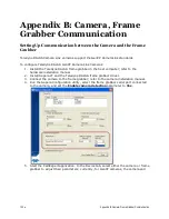
Page 100: ...bber in the host computer refer to the hardware installation manual 2 Install Sapera LT and the Teledyne DALSA frame grabber driver 3 Connect the camera to the frame grabber refer to the camera installation manual 4 Run the Sapera Configuration utility select the frame grabber serial port connected to the camera and set the Enable camera detection parameter to Yes 5 Start the CamExpert application...

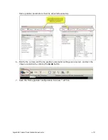
Page 101: ...on 101 frame grabber parameters must be adjusted separately 6 Modify the camera and frame grabber parameter settings as required and test the image acquisition by clicking the Grab button 7 Save the frame grabber configuration to a new ccf file ...

Page 102: ...le contamination using an ionized air gun Place the sensor under the microscope at a magnification of 5x to determine the location of any remaining contamination Clean the contamination on the sensor using one drop of E2 on a swab Wipe the swab from left to right or right to left but only in one direction Do this in an overlapping pattern turning the swab after the first wipe and with each subsequ...

Page 103: ...calibration is done when the sensor is not exposed to light This calibration is used to find and replace pixels that turn hot at longer exposure times Therefore the calibration should be performed after the Offset calibration has been performed The Pixel replacement calibration is performed as follows The camera averages several see flatfieldCalibrationSampleSize images For each pixel o The offset...

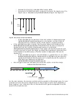
Page 104: ...et By default the replacement threshold is set to the highest correctable value so that the number of dead pixels that are not replaced is 0 o If the calculated pixel gain is not correctable i e greater than 1 5 or 2 when flatfieldCalibrationGainMode isHighResolution or HighGain but less than the replacement threshold then the gain is set to maximum and the number of dead pixels not replaced is in...

Page 105: ...it is possible to use the functions of clserxxx dll or clallserial dll as defined in the Camera Link Specification Figure 38 Serial DLL hierarchy as mentioned in the Camera Link Specification Putting Camera in TLC Mode The camera boots up in GenICam GenCP mode at 9600 baud 8 bits No Parity 1 Stop Bit To put the camera into three letter command mode 1 Power cycle the cameraNote 1 2 Start a serial c...

Page 106: ...s to map the Camera Link serial port to a virtual serial port on the host PC In Sapera use the Sapera Configuration Application to specify which of the PCs Com ports will be mapped to Camera Link Getting Started When the camera is in three letter command mode it will send a prompt i e to indicate that it is ready for input If the previous command was successful then it will send an OK prompt If th...

Page 107: ...t Release 6 Notes The values will be rounded to the nearest increment Changing the aspect ratio will change the values of the AOI Full Name area of interest width Mnemonic aiw Argument s width 512 to max width Max width determined by model and aspect ratio In increments of 128 GenICam Width Release 6 Notes The values will be rounded to the nearest increment Changing the aspect ratio will change th...

Page 108: ...ode taps Mnemonic clm Argument s taps 8 8 camera link taps 10 10 camera link taps GenICam deviceTapCount Release 6 Notes The tap count must match what the framegrabber is expecting Full Name calibrate prnu correction Mnemonic cpa Argument s target The percentage of full scale to use as calibration target monochrome models only gain mode The gain mode used in the calibration HG High Gain HR High Re...

Page 109: ...fieldCalibrationClearCoefficient Release 6 Notes Only available when flat field mode is set to calibration i e ffm CAL Clears the current set selected by the fsc command Full Name flatfield copy from Mnemonic fcf Argument s source F Copy from factory set 1 Copy from set 1 2 Copy from set 2 3 Copy from set 3 4 Copy from set 4 GenICam flatfieldCoefficientsCopyInCurrent Release 6 Notes Only available...

Page 110: ...rectable Dead Pixels 123 Dead Pixels Not Replaced 0 Offset Pixels Clipped 2 Gain Pixels Clipped 0 OK Full Name flatfield mode Mnemonic ffm Argument s mode OFF No flatfield correction ALL Apply both FPN and PRNU correction FPN Apply FPN correction only PRNU Apply PRNU correction only CAL Put camera in calibration mode GenICam flatfieldCorrectionMode Release 6 Notes Calibration mode available only i...

Page 111: ...ix E Three Letter Commands 111 Full Name get camera model Mnemonic gcm GenICam DeviceModelName Release 6 Notes Returns a string containing the model name Full Name get camera parameters Mnemonic gcp Release 6 ...

Page 112: ...1 00 Green Red Gain 1 00 Blue Gain 1 00 Green Blue Gain 1 00 An Coarse Gain 2 Analog Offset 0 Backgd Subtract 0 Aspect Ratio 4 to 3 Sensor Bit Depth 8 bpp Test Image FPN Diagonal Ramp Test Static Value 0 CameraLink Taps 10 taps Serial Baud Rate 460800 AOI x y w h 0 0 3328 2502 Trigger Mode External Trigger Source CC1 Trigger Delay 0 us General Purpose Input Settings Input Threshold 2 4 V Name Debo...

Page 113: ... L1 get status of general purpose input 1 line1 L2 get status of general purpose input 2 line2 CC1 get status of camera control line 1 CC1 CC2 get status of camera control line 2 CC2 CC3 get status of camera control line 3 CC3 CC4 get status of camera control line 4 CC4 L3 get status of general purpose output 1 line3 L4 get status of general purpose output 2 line4 GenICam LineSelector LineStatus R...

Page 114: ...mmand Full Name pixel replacement algorithm Mnemonic pra Argument s algorithm 1 Average and Replace 2 adjacent pixels 3 Average and Weighted Average 2 adjacent pixels GenICam flatfieldCorrectionPixelReplacementAlgorithm Release 6 Notes Full Name pixel replacement mode Mnemonic prm Argument s mode OFF Don t replace ON Replace GenICam flatfieldCorrectionPixelReplacementMode Release 6 Notes Controls ...

Page 115: ...o Argument s offset 0 923 the dn to subtract from the cam GenICam BlackLevelSelector AnalogAll1 BlackLevel Release 6 Notes Applies the offset correction to all analog taps See processing chain for more information Full Name set aspect ratio Mnemonic sar Argument s ratio 2 Aspect 4to3 3 Aspect 1to1 GenICam sensorResolutionAspectRatio Release 6 Notes Does not apply to 12M models They have only a 4 t...

Page 116: ...tionLevel Release 6 Notes Only applies to general purpose input Full Name set exposure mode Mnemonic sem Argument s Mode w Trigger Width t Timed GenICam ExposureMode Release 6 Notes Not available when stm i It will be forced to timed Full Name set exposure time Mnemonic set Argument s time 20 4000000 us external trigger 20 1 FrameRate overhead us internal trigger GenICam ExposureTime Release 6 Not...

Page 117: ...eriod Release 6 Notes Full Name set line inverter Mnemonic sli Argument s line L1 general purpose input 1 L2 general purpose input 2 CC1 cameralink control line 1 CC2 cameralink control line 2 CC3 cameralink control line 3 CC4 cameralink control line 4 L3 general purpose output 1 L4 general purpose output 2 mode OFF ON GenICam LineSelector LineInverter Release 6 Notes See digitial I O for more inf...

Page 118: ...eSelector outputLineSource Release 6 Notes Defines the internal signal to output on the specified general purpose output line Full Name set output pulse delay Mnemonic soy Argument s line L3 general purpose output 1 L4 general purpose output 2 delay 1 8388608 µs GenICam LineSelector outputLinePulseDelay Release 6 Notes The amount of time in milliseconds to delay the output pulse after detecting a ...

Page 119: ...when the camera is externally triggered Full Name set system gain Mnemonic ssg Argument s gain 0 001 7 999 in increments of 1 1024 GenICam GainSelector DigitalAll1 Gain Release 6 Notes Expressed as a multiplication factor See processing chain for more information Full Name set software latch Mnemonic ssl Argument s Line L3 general purpose output 1 L4 general purpose output 2 Mode On software latch...

Page 120: ...ntrol line 3 CC4 cameralink control line 4 S Software GenICam TriggerSource Release 6 Notes Full Name set video mode Mnemonic Svm Argument s mode 0 Video 1 Grey Horizontal Ramp 2 Grey Vertical Ramp 3 Purity 6 Grey Diagonal Ramp 7 FPN Diagonal Ramp 8 PRNU 13 Sensor Static Pattern 1 15 Sensor Dynamic Pattern 1 17 Static Value 18 FPN Coefficients GenICam testImageSelector Release 6 Notes Full Name Te...

Page 121: ...ory Set 1 User Set 1 2 User Set 2 3 User Set 3 4 User Set 4 GenICam UserSetDefaultSelector Release 6 Notes Specifies the set to load upon startup Full Name load user set Mnemonic usl Argument s set name F Factory Set 1 User Set 1 2 User Set 2 3 User Set 3 4 User Set 4 GenICam UserSetSelector UserSetLoad Release 6 Notes Full Name Save user set Mnemonic uss Argument s set name 1 User Set 1 2 User Se...

Page 122: ...80 8M100 XX R FA 81 8M100 XX R FA 80 4M180 XX R FA 81 4M180 XX R fulfill s the requirements of the standard s Radiated emissions requirements EN 55022 2006 EN 55011 2009 ICES 003 CISPR 22 1993 CISPR 11 FCC Part 15 Immunity to disturbances EN55024 1998 EN 61326 1 2006 Place of Issue Waterloo ON CANADA Date of Issue June 1 2011 Name and Signature of authorized person Hank Helmond Quality Manager Tel...

Page 123: ... blue green blue QE graph added EMC Compliance test results added 17 Apr 13 03 Added three letter commands and added new features for version 6 of the microcode Gain Selector command AnalogAllRaw1 and AnalogAllRaw2 values added sensorFirstFrameClearMode command added sensorPRPtime command added flatfieldCorrectionPixelReplacementAlgorithm s revised flatfieldCalibrationPixelReplacementGainThreshold...

Page 124: ...rame rate programmable exposure time 40 externally controlled 39 internally controlled 39 exposure modes descriptions of 38 exposure time set 40 F factory settings 27 frame rate set 40 frame rates 10 G grounding instructions 20 GUI overview 22 I I O control 42 image acquisition 38 Input Output control 42 input output 19 interface mechanical 9 L LED definitions 21 line rate 41 M mechanical camera 1...

Page 125: ...random noise 9 requirements PC 18 responsivity 9 graph 12 revision history 124 S safety 6 settings factory 27 setup overview 18 software required 8 specifications mechanical 9 operating 9 10 performance 9 T trigger modes 50 ...

Reviews: