50
•
Camera Operation
Notes
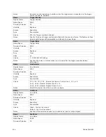
Specifies the most and least significant bits that define the externally controlled gain
factor.
MSB
LSB
Gain Factor
0
0
1x
0
1
2x
1
0
4x
1
1
8x
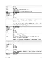
Invisible Features
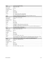
Name
streamingGPIOLineSelector
Name Space
Custom
Firmware Release
04
Visibility
Invisible
Notes
Internal use. To implement feature streaming.
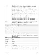
Name
streamingGPIO
Name Space
Custom
Firmware Release
04
Visibility
Invisible
Notes
Internal use. To implement feature streaming.
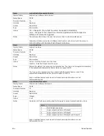
Name
streamingGPOLineSelector
Name Space
Custom
Firmware Release
04
Visibility
Invisible
Notes
Internal use. To implement feature streaming.
Trigger Modes
The camera’s image exposures are initiated by a trigger signal The trigger event is either a
programmable internal signal used in free running mode, an external input used for
synchronizing exposures to external triggers, or a programmed function call message by the
controlling computer. These triggering modes are described below.
•
Free running (trigger disabled): The camera free-running mode has a programmable
internal timer for frame rate and a programmable exposure period.
•
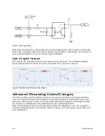
External trigger: Exposures are controlled by an external trigger signal. The external
trigger signal can be either a Camera Link control line (i.e. CC [4 : 1]) or a general
purpose input (e.g. GPIO [2 : 1]. General purpose inputs are isolated by an opto-
coupler input with a time programmable debounce circuit.
•
Software trigger: An exposure trigger is sent as a control command via the Camera
Link serial communications interface. Software triggers cannot be considered time
accurate due to communications latency and sequential command jitter.
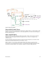
I/O Block Diagram
The following diagram describes the Input/Output features of the camera and how they are
related.


