Page Mode
CAN-CBM-DP
Software Manual Rev. 2.0
48
6.4.3 Page Structure
The maximum length of the page depends on the configuration of addresses, made by the user (see page
45).
On all pages the first eight bytes contain information which is required for the protocol-controlled
exchange of pages between PLC and gateway. They are followed by the ‘user data’ of the page. During
configuration this data contains, e.g., the definition of identifiers, during operation the data of the
identifiers.
Byte
0
1
2
3
4
5
6
7
8
9
10
11
12
13
14
15
16
...
Length
[bytes]
2
6
depending on page no.
...
Content
page no.
protocol data
user data
...
Example
51
...
e.g. Tx-identifier definition
...
Table 6.4.2:
Structure of pages
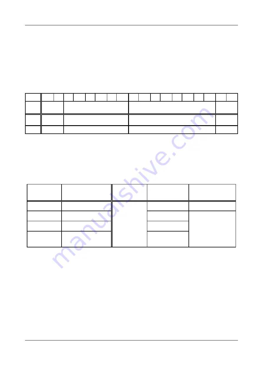
The first two bytes of each segment of a page specify the page number. The page number marks the
page to be transmitted and the type of page. The following table shows the page numbers, page types
and the functional and data blocks which are available.
Page number
Page type
Function
block
Data block
Formal operand
ENABLE
0
setup page
FB2
-
0
51...150
Tx-configuration
DB94
1
151...250
Rx-configuration
DB95
t
251
data exchange
output: DB96
input:
DB97
Table 6.4.3:
Overview of pages
The contents of bytes 3 to 7, the ‘protocol data’ will not be referred to. Please use the function block
(FB2) contained in the product package to control the transmission of pages. It contains the commands
required for the protocol control.
The following chapters will describe the page types.


