B-72
B90 Low Impedance Bus Differential System
GE Multilin
B.4 MEMORY MAPPING
APPENDIX B
B
F500
UR_UINT16: PACKED BITFIELD
First register indicates input/output state with bits 0 (MSB) to 15
(LSB) corresponding to input/output state 1 to 16. The second reg-
ister indicates input/output state with bits 0 to 15 corresponding to
input/output state 17 to 32 (if required) The third register indicates
input/output state with bits 0 to 15 corresponding to input/output
state 33 to 48 (if required). The fourth register indicates input/out-
put state with bits 0 to 15 corresponding to input/output state 49 to
64 (if required).
The number of registers required is determined by the specific
data item. A bit value of 0 = Off and 1 = On.
F501
UR_UINT16: LED STATUS
Low byte of register indicates LED status with bit 0 representing
the top LED and bit 7 the bottom LED. A bit value of 1 indicates
the LED is on, 0 indicates the LED is off.
F502
BITFIELD: ELEMENT OPERATE STATES
Each bit contains the operate state for an element. See the F124
format code for a list of element IDs. The operate bit for element ID
X is bit [X mod 16] in register [X/16].
F519
ENUMERATION: NON-VOLATILE LATCH
0 = Reset-Dominant, 1 = Set-Dominant
F523
ENUMERATION: DNP OBJECTS 20, 22, AND 23 DEFAULT
VARIATION
F524
ENUMERATION: DNP OBJECT 21 DEFAULT VARIATION
F525
ENUMERATION: DNP OBJECT 32 DEFAULT VARIATION
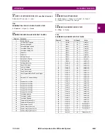
F530
ENUMERATION: FRONT PANEL INTERFACE KEYPRESS
F531
ENUMERATION: LANGUAGE
0 = English, 1 = French, 2 = Chinese, 3 = Russian, 4 = Turkish, 5 =
German
F600
UR_UINT16: FLEXANALOG PARAMETER
Corresponds to the Modbus address of the value used when this
parameter is selected. Only certain values may be used as Flex-
Analogs (basically all metering quantities used in protection).
F601
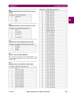
ENUMERATION: COM2 PORT USAGE
Bitmask
Default variation
0
1
1
2
2
5
3
6
Bitmask
Default variation
0
1
1
2
2
9
3
10
Bitmask
Default variation
0
1
1
2
2
3
3
4
4
5
5
7
Valu
e
Keypress
Valu
e
Keypress
Valu
e
Keypress
0
None
15
3
33
User PB 3
1
Menu
16
Enter
34
User PB 4
2
Message Up
17
Message
Down
35
User PB 5
3
7
~
18
0
~
36
User PB 6
4
8
19
Decimal
37
User PB 7
5
9
20
+/–
38
User PB 8
6
Help
21
Value Up
39
User PB 9
7
Message Left
22
Value Down
40
User PB 10
8
4
23
Reset
41
User PB 11
9
5
24
User 1
42
User PB 12
10
6
25
User 2
44
User 4
11
Escape
26
User 3
45
User 5
12
Message
Right
31
User PB 1
46
User 6
13
1
32
User PB 2
47
User 7
14
2
Enumeration
COM2 port usage
0
RS485
1
RRTD
2
GPM-F
3
RRTD and GPM-F
Summary of Contents for B90
Page 10: ...x B90 Low Impedance Bus Differential System GE Multilin TABLE OF CONTENTS ...
Page 284: ...5 166 B90 Low Impedance Bus Differential System GE Multilin 5 8 TESTING 5 SETTINGS 5 ...
Page 334: ...10 8 B90 Low Impedance Bus Differential System GE Multilin 10 2 BATTERIES 10 MAINTENANCE 10 ...
Page 338: ...A 4 B90 Low Impedance Bus Differential System GE Multilin A 1 PARAMETER LISTS APPENDIX A A ...
Page 460: ...C 30 B90 Low Impedance Bus Differential System GE Multilin C 7 LOGICAL NODES APPENDIX C C ...
Page 476: ...E 10 B90 Low Impedance Bus Differential System GE Multilin E 1 IEC 60870 5 104 APPENDIX E E ...
Page 502: ...viii B90 Low Impedance Bus Differential System GE Multilin INDEX ...

