Rev. 2.10
168
���� 02� 201�
Rev. 2.10
169
���� 02� 201�
HT68F20/HT68F30/HT68F40/HT68F50/HT68F60
HT68FU30/HT68FU40/HT68FU50/HT68FU60
Enhanced I/O Flash Type 8-Bit MCU with EEPROM
HT68F20/HT68F30/HT68F40/HT68F50/HT68F60
HT68FU30/HT68FU40/HT68FU50/HT68FU60
Enhanced I/O Flash Type 8-Bit MCU with EEPROM
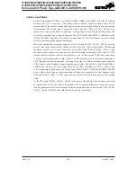
Comparator Interrupt
Each also possesses its own interrupt function. When any one of the changes state, its relevant
interrupt flag will be set, and if the corresponding interrupt enable bit is set, then a jump to its
relevant interrupt vector will be executed. Note that it is the changing state of the C0OUT or C1OUT
bit and not the output pin which generates an interrupt. If the microcontroller is in the SLEEP or
IDLE Mode and the Comparator is enabled, then if the external input lines cause the Comparator
output to change state, the resulting generated interrupt flag will also generate a wake-up. If it is
required to disable a wake-up from occurring, then the interrupt flag should be first set high before
entering the SLEEP or IDLE Mode.
Programming Considerations
If the comparator is enabled, it will remain active when the microcontroller enters the SLEEP or
IDLE Mode, however as it will consume a certain amount of power, the user may wish to consider
disabling it before the SLEEP or IDLE Mode is entered.
As comparator pins are shared with normal I/O pins the I/O registers for these pins will be read as
zero (port control register is "1") or read as port data register value (port control register is "0") if the
comparator function is enabled.
Serial Interface Module – SIM
These devices contain a Serial Interface Module, which includes both the four line SPI interface or
the two line I
2
C interface types, to allow an easy method of communication with external peripheral
hardware. Having relatively simple communication protocols, these serial interface types allow the
microcontroller to interface to external SPI or I
2
C based hardware such as sensors, Flash or EEPROM
memory, etc. The SIM interface pins are pin-shared with other I/O pins therefore the SIM interface
function must first be selected using a configuration option. As both interface types share the same
pins and registers, the choice of whether the SPI or I
2
C type is used is made using the SIM operating
mode control bits, named SIM2~SIM0, in the SIMC0 register. These pull-high resistors of the SIM
pin-shared I/O are selected using pull-high control registers, and also if the SIM function is enabled.


