74
**
Proceed as follows to identify the position of the faulty valve:
Error code HEX – 0x20 = n
Convert the n code from hexadecimal to decimal. The resulting number corresponds to the faulty position. The positions where dummy or bypass valves are installed must also be
considered in the calculation. Codes are numbered from zero to 127. Code 0 corresponds to the first valve of the island.
For example: error code
0x20
n= 0x20 – 0x20 = 0x00
decimal value = 0 corresponding to the first valve (position) of the island.
error code
0x3F
n= 0x3F – 0x20 = 1F
decimal value = 31 corresponding to the valve (position) 32
.
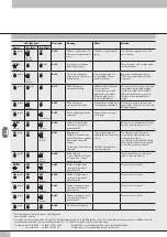
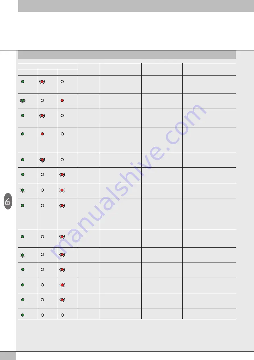
LED light state
Hex code
Meaning
Notes
Solution
Power
Bus Error
Local Error
ON
(green)
RED
(double
flashing)
OFF
0x16
Address / configuration of a
valve base or a signal module
error
Valve base or signal module
faulty
Turn off power supply and remove the
cause of failure
GREEN
(flashing)
OFF
ON
(red)
0x15
Power supply out of range
(Under/over-voltage)
-
Power the system with a voltage within
the allowed range
ON
(green)
RED
(single
flashing)
OFF
0x14
Error in the configuration
parameters of a valve base or
a signal module
Current configuration not
corresponding to the one
stored in the device.
Repeat the configuration procedure.
If the error persists, replace the faulty
component.
ON
(green)
ON
(red)
OFF
0x10
EB 80 Net internal
communication faulty
Additional island configured
but not connected.
Connection between valve
bases faulty or incomplete
(blind end plate C is not
correct for the fieldbus).
Check the correct connection of the entire
system. Make sure the blind end plate
is of the type suitable for the fieldbus.
When the communication is restored,
the alarm rests automatically after 3
seconds.
ON
(green)
RED
(flashing)
OFF
0x0F
EB 80 Net internal
communication disturbed.
Communication is faulty due to
electromagnetic disturbances.
Move the power cables away from the
signal cables. Check the noise levels with
the EB 80 Manager.
ON
(green)
OFF
RED
(
single flashing)
0x09
Error in configuring the head
parameters.
At least a value is wrong or
out-of-range.
-
GREEN
(flashing)
OFF
RED
(flashing)
0x08
Number of solenoid pilots
connected to the network
greater than 128
-
Restore correct configuration of the valve
bases, by removing any excess ones.
ON
(green)
OFF
RED
(double
flashing)
0x07
Mapping error.
Number of connected valve
bases different from or greater
than the max. admissible
number.
Closing plate on S modules not
connected.
Current configuration not
matching the one stored in the
device.
The EB 80 Net network not
properly completed.
Turn off power supply. Restore the
correct configuration and repeat the
configuration procedure.
Turn off power supply, install the closing
plate using the terminal board provided
or insert the termination connector.
ON
(green)
OFF
RED
(single
flashing)
0x06
Addressing error:
• type of module not allowed;
• no valve base or signal
module connected.
-
Connect the valve bases or the signal
modules of the type allowed.
GREEN
(flashing)
OFF
RED
(flashing)
0x05
Number of digital inputs
connected to the network
greater than 128
-
Disconnect excess modules
ON
(green)
OFF
RED
(flashing)
0x04
Number of digital outputs
connected to the network
greater than 128
-
Disconnect excess modules
ON
(green)
OFF
RED
(flashing)
0x03
Number of analogue inputs
connected to the network
greater than 16
-
Disconnect excess modules
ON
(green)
OFF
RED
(flashing)
0x02
Number of analogue outputs
connected to the network
greater than 16
-
Disconnect excess modules
ON
(green)
OFF
OFF
0x00
The system works properly
-
-
Summary of Contents for EB 80 ETHERNET POWERLINK
Page 1: ...MANUALE D USO USER MANUAL ...


