Interfaces
42 / 94
EN-US · 30.30.01.02237 · 00 · 04/20
Offset
Index
Description
Type
Length
[bytes]
R/W
(Dec)
(Hex)
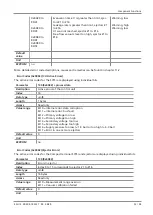
10200
0x27D8
Request: Index
uint16
2
wo
10201
0x27D9
Request: Subindex
uint8
1
wo
10202
0x27DA
Request: RW
bool
1
wo
10203
0x27DB
Request: Length
uint8
1
wo
10204
0x27DC
Request: Data
uint8
232
wo
10205
0x27DD
Request: Trigger
bool
1
wo
10206
0x27DE
Request: Error
uint8
1
ro
10207
0x27DF
Response Result
bool
1
ro
10208
0x27E0
Response: Error Code
uint8
1
ro
10209
0x27E1
Response: Additional Error Code
uint8
1
ro
10210
0x27E2
Response: Error
uint8
1
ro
10211
0x27E3
Response: Trigger
uint8
1
wo
10212
0x27E4
Response: Length
uint8
1
ro
10213
0x27E5
Response: Data
uint8
232
ro
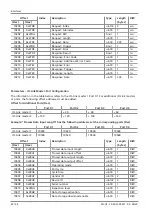
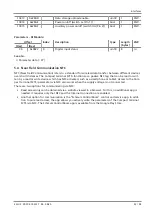
Parameters – IO-Link Master: Port Configuration
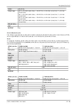
The information in the table below refers to the IO-Link master 1 Port X1. For additional IO-Link masters
or ports, the following offset addresses must be added:
Offset for Additional Ports (Dec)
Port X1
Port X2
Port X3
Port X4
IO-Link master 1
+ 0
+ 20
+ 40
+ 60
IO-Link master 2
+ 100
+ 120
+ 140
+ 160
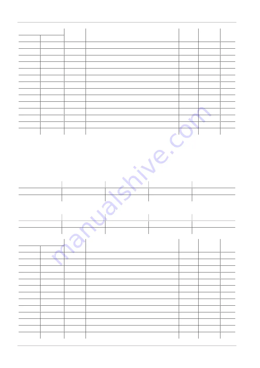
Example: “Process Data Input Length” has the following addresses at the corresponding ports (Dec)
Port X1
Port X2
Port X3
Port X4
IO-Link master 1
10400
10420
10440
10460
IO-Link master 2
10500
10520
10540
10560
Offset
Index
Description
Type
Length
[bytes]
R/W
(Dec)
(Hex)
10400
0x28A0
Process data input length
uint8
1
R/W
10401
0x28A1
Process data input offset
uint8
1
R/W
10402
0x28A2
Process data output length
uint8
1
R/W
10403
0x28A3
Process data output offset
uint8
1
R/W
10404
0x28A4
Operating mode
uint8
1
R/W
10405
0x28A5
Port cycle
uint8
1
R/W
10406
0x28A6
Cycle time
uint8
1
R/W
10407
0x28A7
Vendor ID
uint16
2
R/W
10408
0x28A8
Device ID
uint32
4
R/W
10409
0x28A9
Serial number
uint8
1
R/W
10410
0x28AA
Inspection level
uint8
1
R/W
10411
0x28AB
Data storage activation
uint8
1
R/W
10412
0x28AC
Data storage download enable
uint8
1
R/W


