Component Functions
66 / 94
EN-US · 30.30.01.02237 · 00 · 04/20
6.5 IO-Link Master Functions
Functions of the IO-Link class B master:
•
Process data management (IO-Link device process data is copied to the Ethernet process data)
•
Port configuration
•
IO-Link ISDU – data management (read/write parameter data of IO-Link devices)
•
IO-Link master event handling
6.5.1 Process Data Management
The maximum process data width (input or output process data) per IO-Link master port is defined as 32
bytes. In the Profinet variant, the process data width actually used can be adapted to the process data
width of the connected IO-Link device (e.g. Profinet). This is ensured by configuring the port in the con-
troller using corresponding modules/submodules that are predefined in the device description file. For
other Ethernet variants, the size is fixed at 32 bytes.
--> See 5.2 “Process Data”.
Furthermore, the byte order (endianness) for the corresponding Ethernet variant must be observed.
--> See 5.2 “Process Data”.
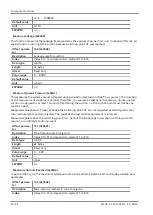
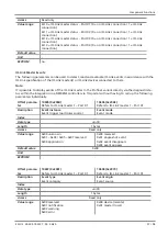
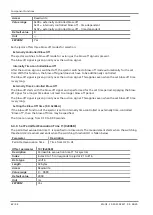
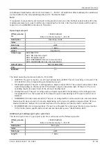
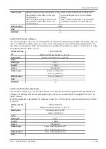
Process Data via Parameter Data
Alternatively, the process data can also be read/written via parameter data:
Offset param-
eter
10600 (0x2968)
10601 (0x2969)
10602 (0x296A)
10603 (0x296B)
Description
Master 1 process
data input
Master 2 process
data input
Master 1 process
data output
Master 2 process
data output
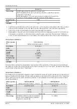
Index
-
Data type
uint8
Length
128 bytes
Access
Read
Read/write
Value range
Byte 0–31: Port X1
Byte 32-63: Port X2
Byte 64-95: Port X3
Byte 96-127: Port X4
Default value
***
Unit
-
EEPROM
no
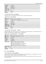
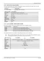
6.5.2 IO-Link Port Configuration
Each port on the IO-Link master can be configured individually.
The configuration is usually carried out using parameter data.
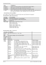
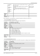
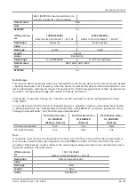
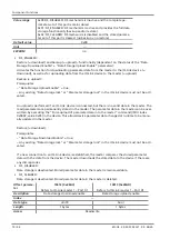
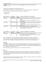
The following port configurations are available:
•
IO-Link device validation
•
Operating mode port
•
Additional port settings (port cycle / cycle time)
•
IO-Link device data storage
•
Switch on/off sensor voltage L+
•
Switch on/off actuator voltage UA
•
Summary: IO-Link master as digital input or digital output module

