Chapter 5 Relay Ladder Logic Programming
110
-
※
The max data length for Mode 1 and 3 is 25 words, it means 25 continuous addresses. The max data length for
Mode 4 is 400bits.
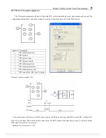
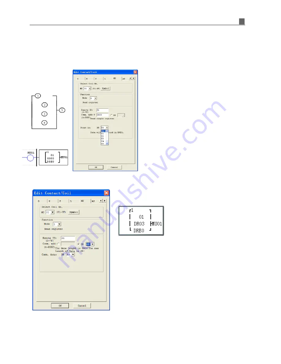
MU mode1: Read Registers
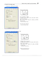
Set parameter
③
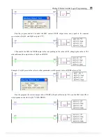
, address, to be constant: as show in below figure, the data length is fixed at 1 (it means read
signal register only).
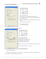
Setting parameter
③
, address refers to the value of DR register:
Function parameter display:
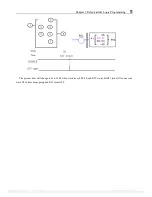
Setting DR03=0001 for the address
Setting DR04=0002 for the data length
(means how many data will be read)
The sending out Modbus command will be:
01 03 00 01 00 02 CRC16;
Received response from slaver:
01 03 04 data1-1 data1-2 data2-1 data2-2 CRC16;
Saving data to DRE0~DRE1:
DRE0 = data1-1 + data1-2
DRE1 = data2-1 + data2-2
※
the max length of data is 25.
The above example shows how to read two data from two different (but continuous) registers/addresses. For
more information, see the SG2 Modbus protocol manual.
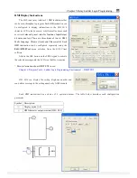
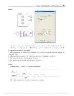
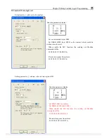
Address is a constant, 0003.
Data length is fixed at 1word, in other
word, just one address.
The sending out Modbus command will be:
01 03 00 03 00 01 CRC16;
Received response form slaver:
01 03 02 data1-1 data1-2 CRC16;
Saving date to DRE0:
DRE0 = data1-1 + data1-2
※
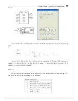
Note:
The completed data in a register is a 16 bits
type. When using Modbus protocol, this 16 bits
data is going to be divided into high 8 bits and
low 8 bits. In above example:
Data1-1 is the high 8 bits
Data1-2 is the low 8 bits
PDF compression, OCR, web optimization using a watermarked evaluation copy of CVISION PDFCompressor

