Chapter 6 FBD Block Diagram Programming
135
※
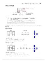
Logic Block include: AND, AND EDGE, NAND, NAND EDGE, OR, NOR, XOR, NOT, RS, PULSE,
BOOLEAN. Each logic block occupied a BLOCK; the available number is limited by the number of B and system
memory space. Logic function blocks source show as blow table:
Logic
Block number
System memory (byte)
AND 1 8
AND(EDGE) 1
8
NAND 1
8
NAND(EDGE) 1
8
OR 1 8
NOR 1 8
XOR 1 6
RS 1 6
NOT 1 4
PULSE 1
4
BOOLEAN 1
12
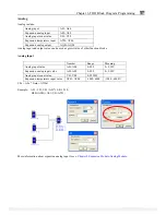
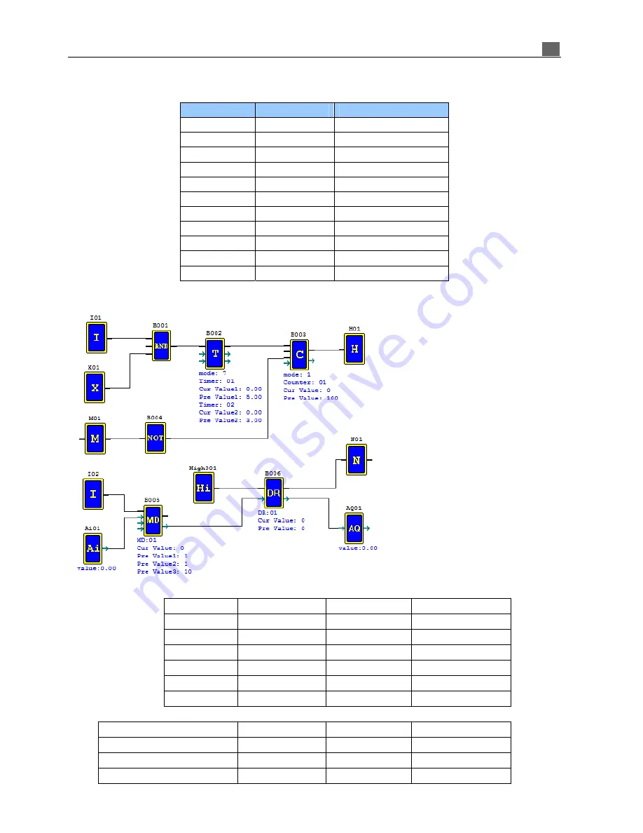
Example: calculating resources
Number
Function / Logic
Memory bytes
Function number
B001 AND
8
B002 Timer
mode
7 12
T01,
T02
B003 Counter
mode
1
14
C01
B004 NOT
4
B005 MD
11
MD01
B006 DR
register 6
DR01
B number
Memory bytes
Memory space limits in SG2
260
2600
Resource used by program
6
55
Still available in SG2
254
2545
Input coils: I01, X01, M01, I02;
Output coils: H01, N01;
Normal ON: Hi001;
Analog input: A01;
Analog output: AQ01;
Logic and function block: B001~B006.
Coil input/output and analog input/output
don’t occupied B number and memory
space.
PDF compression, OCR, web optimization using a watermarked evaluation copy of CVISION PDFCompressor

