Chapter 5 Relay Ladder Logic Programming
115
-
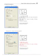
Example
:
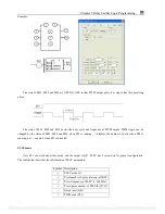
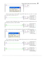
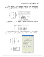
MU sending and receiving data via RS485 port when it’s enabled. Here recommends user to put the D-trigger
element in front of the MU coil.
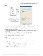
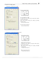
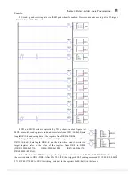
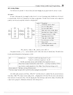
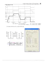
MU01 and MU05 coils are controlled by T01 as shown in above figure. Set
MU01 as mode1, read registers mode, address starts from DR11=14=0x0E, data
length DR12=4, and saving data to the registers from DR01 to DR04.
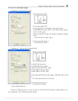
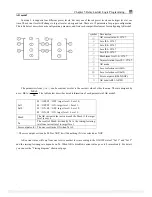
Setting MU05 as mode3, write multiple registers mode, address
DR13=14=0x0E, data length DR14=4, and the data which want to write into
target registers refer to the value of the register, from DR05 to DR08
(DR05=10000=0x2710, DR06=8000=0x1F40, DR07=6000=0x1770,
DR08=4000=0x0FA0);
When T01 turns ON, MU01 is going to be triggered to send command 01 03 00 0E 00 04 CRC16, then saving
the received data to DR01~DR04. After 0.2s T01 OFF, then trigger MU05 sending command 01 10 00 0E 00 04 08
27 10 1F 40 17 70 0F A0 CRC16, writing 4 sets data to the registers (0x0E~0x11) in the slaver.
PDF compression, OCR, web optimization using a watermarked evaluation copy of CVISION PDFCompressor


