AMY-5M
-
Hardware
Integration
Manual
Objective
Specification
Contents
GPS.G5-MS5-08207
u-blox
proprietary
Page 5
your position is our focus
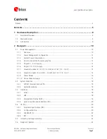
Contents
Preface ............................................................................................................................................................ 3
Contents..............................................................................................................................5
1
Hardware Description ..................................................................................................8
1.1
Functional
Overview ............................................................................................................................. 8
1.2
Module
Features................................................................................................................................... 8
1.3
Architecture.......................................................................................................................................... 9
2
Design-In.....................................................................................................................10
2.1
Power
Management ........................................................................................................................... 10
2.1.1
Overview ..................................................................................................................................... 10
2.1.2
Power
Management
Configuration ............................................................................................. 12
2.1.3
System
Power
Consumption........................................................................................................ 12
2.1.4
How
to
connect
the
Power
Supply
Pins ....................................................................................... 13
2.1.5
Single
2.5…3.6
V
Supply............................................................................................................. 13
2.1.6
Single
1.75…2.0
V
Supply........................................................................................................... 14
2.1.7
Separate
Supplies
of
1.8
V
(1.75…2.0V)
and
1.4
V
(1.4…3.6
V).................................................. 15
2.1.8
Separate
Supplies
of
3.0
V
(2.5…3.6
0V)
and
1.4
V
(1.4…3.6
V)................................................. 16
2.1.9
Power
Modes .............................................................................................................................. 16
2.1.10
Active
Antenna
Supply ................................................................................................................ 17
2.2
System
Functions ................................................................................................................................ 18
2.2.1
EXTINT
-
External
Interrupt
Pin..................................................................................................... 18
2.2.2
System
Monitoring ...................................................................................................................... 18
2.3
Interfaces............................................................................................................................................ 18
2.3.1
Serial ........................................................................................................................................... 18
2.3.2
USB ............................................................................................................................................. 18
2.3.3
Display
Data
Channel
(DDC) ........................................................................................................ 19
2.3.4
Synchronous
Peripheral
Interface
(SPI) ......................................................................................... 20
2.4
I/O
Pins ............................................................................................................................................... 20
2.4.1
Peripheral
Input
Output
(PIO)....................................................................................................... 20
2.4.2
Configuration
Pins....................................................................................................................... 20
2.4.3
SAFEBOOT_N .............................................................................................................................. 23
2.4.4
RTC ............................................................................................................................................. 23
2.5
Increasing
Jamming
Immunity............................................................................................................. 23
2.6
Design-In
Checklist ............................................................................................................................. 23

