AD9779
Preliminary Technical Data
Rev. PrD | Page 12 of 34
GENERAL DESCRIPTION
The AD9779 combines many features which make it make it a very
attractive DAC for wired and wireless communications systems.
The dual digital signal path and dual DAC structure allow an easy
interface with common quadrature modulators when designing
single sideband transmitters. The speed and performance of the
AD9779 allow wider bandwidths/more carriers to be synthesized
than with previously available DACs. The digital engine in the
AD9779 uses a breakthrough filter architecture that combines the
interpolation with a digital quadrature modulator. This allows the
AD9779 to do digital quadrature frequency up conversion. The
AD9779 also has features which allow simplified synchronization
with incoming data, and also allows multiple AD9779s to be
synchronized.
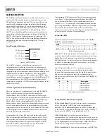
Serial Peripheral Interface
AD9779
SPI
PORT
SPI_CSB (pin 69)
SPI_SCLK (pin 68)
SPI_SDI (pin 67)
SPI_SDO (pin 66)
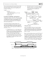
Figure 24. AD9779 SPI Port
The AD9779 serial port is a flexible, synchronous serial
communications port allowing easy interface to many industry-
standard microcontrollers and microprocessors. The serial I/O is
compatible with most synchronous transfer formats, including both
the Motorola SPI® and Intel® SSR protocols. The interface allows
read/write access to all registers that configure the AD9779. Single
or multiple byte transfers are supported, as well as MSB first or LSB
first transfer formats. The AD9779’s serial interface port can be
configured as a single pin I/O (SDIO) or two unidirectional pins for
in/out (SDIO/SDO).
General Operation of the Serial Interface
There are two phases to a communication cycle with the AD9779.
Phase 1 is the instruction cycle, which is the writing of an
instruction byte into the AD9779, coincident with the first eight
SCLK rising edges. The instruction byte provides the AD9779 serial
port controller with information regarding the data transfer cycle,
which is Phase 2 of the communication cycle. The Phase 1
instruction byte defines whether the upcoming data transfer is read
or write, the number of bytes in the data transfer, and the starting
register address for the first byte of the data transfer. The first eight
SCLK rising edges of each communication cycle are used to write
the instruction byte into the AD9779.
A logic high on the CS pin, followed by a logic low, will reset the
SPI port timing to the initial state of the instruction cycle. This is
true regardless of the present state of the internal registers or the
other signal levels present at the inputs to the SPI port. If the SPI
port is in the midst of an instruction cycle or a data transfer
cycle,none of the present data will be written.
The remaining SCLK edges are for Phase 2 of the communication
cycle. Phase 2 is the actual data transfer between the AD9779 and
the system controller. Phase 2 of the communication cycle is a
transfer of 1, 2, 3, or 4 data bytes as determined by the instruction
byte. Using one multibyte transfer is the preferred method. Single
byte data transfers are useful to reduce CPU overhead when
register access requires one byte only. Registers change immediately
upon writing to the last bit of each transfer byte.
Instruction Byte
The instruction byte contains the information shown in
Error!
Reference source not found.
.
MSB
LSB
I7 I6 I5 I4 I3 I2 I1 I0
R/W N1 N0 A4 A3 A2 A1 A0
Table 9. SPI Instruction Byte
R/W
,
Bit 7 of the instruction byte, determines whether a read or a
write data transfer will occur after the instruction byte write. Logic
high indicates read operation. Logic 0 indicates a write operation.
N1, N0
, Bits 6 and 5 of the instruction byte, determine the number
of bytes to be transferred during the data transfer cycle. The bit
decodes are shown in Table 10.
A4, A3, A2, A1, A0
, Bits 4, 3, 2, 1, 0 of the instruction byte,
determine which register is accessed during the data transfer
portion of the communications cycle. For multibyte transfers, this
address is the starting byte address. The remaining register
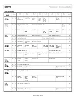
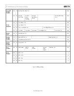
addresses are generated by the AD9779 based on the LSBFIRST bit
(REG00, bit 6).
N1
N2
Description
0
0
Transfer 1 Byte
0
1
Transfer 2 Bytes
1
0
Transfer 3 Bytes
1
1
Transfer 4 Bytes
Table 10. Byte Transfer Count
Serial Interface Port Pin Descriptions
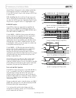
SCLK—Serial Clock
. The serial clock pin is used to synchronize
data to and from the AD9779 and to run the internal state
machines. SCLK’s maximum frequency is 20 MHz. All data input
to the AD9779 is registered on the rising edge of SCLK. All data is
driven out of the AD9779 on the falling edge of SCLK.
CSB—Chip Select
. Active low input starts and gates a
communication cycle. It allows more than one device to be used on
the same serial communications lines. The SDO and SDIO pins will
go to a high impedance state when this input is high. Chip select
should stay low during the entire communication cycle.
SDIO—Serial Data I/O
. Data is always written into the AD9779 on


