Debug Support
Copyright © ARM Limited 2000. All rights reserved.
8-13
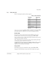
These are arranged as shown in Table 8-3.
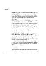
The three control bits are:
•
SYSSPEED
•
WPTANDBKPT
•
a reserved bit.
While debugging, the value placed in the SYSSPEED control bit determines if the
ARM9E-S core executes the instruction at system speed.
After the ARM946E-S has entered debug state, the first time SYSSPEED is captured
and scanned out tells the debugger whether the core has entered debug state due to a
breakpoint (SYSSPEED LOW) or a watchpoint (SYSSPEED HIGH). A watchpoint
and a breakpoint can occur simultaneously. When a watchpoint condition occurs, the
WPTANDBKPT bit must be examined by the debugger to determine whether the
instruction currently in the Execute stage of the pipeline is breakpointed. If it is,
WPTANDBKPT is HIGH, otherwise it is LOW.
8.4.2
Scan chain 2
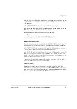
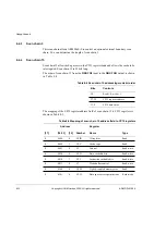
Scan chain 2 allows access to the EmbeddedICE-RT logic registers.The order of the
scan chain, from DBGTDI to DBGTDO, is:
•
read/write
•
register address bits 4:0
•
data value bits 31:0.
No action occurs during CAPTURE-DR.
During SHIFT-DR, a data value is shifted into the serial register. Bits 36:32 specify the
address of the EmbeddedICE-RT register to be accessed.
During UPDATE-DR, this register is either read or written depending on the value of
bit 37 (0 = read, 1 = write).
Table 8-3 Scan chain 1 bits
Bit
Function
67:35
Data values
34:32
Control bits
31:0
Instruction values
Summary of Contents for ARM946E-S
Page 1: ...ARM DDI 0155A ARM946E S Technical Reference Manual ...
Page 6: ...vi Copyright ARM Limited 2000 All rights reserved ARM DDI 0155A 04 Limited Confidential ...
Page 54: ...Programmer s Model 2 34 Copyright ARM Limited 2000 All rights reserved ARM DDI 0155A ...
Page 70: ...Caches 3 16 Copyright ARM Limited 2000 All rights reserved ARM DDI 0155A ...
Page 78: ...Protection Unit 4 8 Copyright ARM Limited 2000 All rights reserved ARM DDI 0155A ...
Page 112: ...Coprocessor Interface 7 14 Copyright ARM Limited 2000 All rights reserved ARM DDI 0155A ...


