U
nd
er
sta
nd
in
g
th
e
F
ea
tu
re
s
U
nd
er
sta
nd
in
g
th
e
F
ea
tu
re
s
3--3
Installation and Specifications
Status and Control Registers
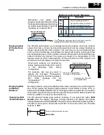
The OP-panels communicate to the PLC through user defined PLC data registers.
The starting or “Base” register is assigned during panel configuration and
automatically occupies fourteen consecutive 16--bit data registers. In this manual
the registers are identified as M+0, M+1, M+2, thru M+13. Each OptiMate panel
which is connected to the PLC maintains separate Status and Control registers
within the PLC. These registers (M+12, M+13) contain information to monitor and
control individual OP-panel functions and features. Shown in the figure below, base
registers M+12 and M+13
must have
bit level access by the user control program.
That means Status and Control
word
register memory (OP-panel Base registers)
must be mapped to user memory bit registers. These bit registers are referred to as
Internal Control Relays such as C0, C1, etc.
NOTE:
Depending on which CPU is used and the Base memory which is assigned, the
Status and Control registers
may not
require the mapping process.
Once again, the Status and Control bits are monitored and manipulated by the PLC
ladder logic. For discrete operations such as pushbuttons and lamps, the registers
M+12 and M+13 bits are accessed by the PLC control program. The figure below
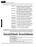
shows the fixed definition of the Status and Control register bits. These bits are
labeled F1--F5 (Pushbuttons), L1--L3 (Lamps), for example. The bits and associated
labels are described on the following page. First examine the figure below to begin
understanding the OP-panel registers and functions. You must structure your ladder
logic program to coordinate OP-panel functions asynchronously. This means the
operations are triggered successively--not by a clock, but by the completion of an
operation.
Top line data 2 (for long BCD and floating point numbers)
Status Register M+12
LSB
Top line message selection
Second line message selection
Third line message selection
Bottom line message selection
Top line data
Second line data
Function
M+0
M+1
M+2
M+5
M+6
Register
F5
F1
F2
F3
F4
12
13
14
15
8
9
10
11
4
5
6
7
0
1
2
3
M+3
M+4
PLC
Register
Bottom line data 2 (for long BCD and floating point numbers)
Second line data 2 (for long BCD and floating point numbers)
Third line data
Third line data 2 (for long BCD and floating point numbers)
Control register
Bottom line data
Status register
M+7
M+8
M+9
M+12
M+13
M+10
M+11
MSB
Control Register M+13
LSB
LF2
LF3
BD
L1
L2
L3
LF1
12
13
14
15
8
9
10
11
4
5
6
7
0
1
2
3
MSB
Status and Control
Register Overview
Bit Level Access


