U
nd
er
st
an
di
ng
U
nd
er
st
an
di
ng
th
e
F
ea
tu
re
s
th
e
F
ea
tu
re
s
3--8
Installation and Specifications
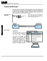
In this example, if the PLC’s input signal X4 is
ON, the 16 bit integer (K10) value is placed in
Word register V2000 (M+0) selecting message
#10 to be displayed on the top line. The data val-
ue in register V3000 (let’s say 1100) is moved
into V2004 (M+4), which is embedded in the top
line message. The top line data value will update
as long as X4 is enabled (ON).
X4
LD
K10
OUT
V2000
Selects message#
for Top line
M+0
ON
V2000 = 10
M+4
Top line message data
Message # requested
M+0
V2004 = 1100
Example PLC
User Memory
OP-Panel
Register
LD
V3000
OUT
V2004
Loads variable data
M+4
Remember,
your
ladder
logic
program must select the message
being displayed by placing an
integer value between 1 and 160
(message #) in register M+0. The
embedded data for the top line
message is controlled by loading a
16 bit value into register M+4.
Top Line Dynamic Message
Zone1 Temp. = 1100
Example Message #5
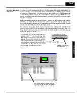
The highlighted registers M+0 and M+4 in this figure
result in displaying this top-line dynamic message.
Top line message selection
Function
M+0
Register
Value
10
M+1
M+3
M+4
M+5
M+6
Second line message selection
M+2
Bottom line message selection
Top line data
Top line data 2
Second line data
Third line message selection
1100
LD
K12
OUT
V2003
V2003 = 12
Message # requested
M+3
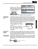
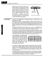
In this example, if the PLC’s X5 input signal is
ON, the 16 bit integer (K12) value is placed in
Word register V2003 (M+3) requesting message
#12 to be displayed on the bottom line. The data
value in register V3001 (let’s say 1101) is moved
into V2012 (M+10), which is embedded in the
bottom line message. The bottom line data value
will update as long as X5 is enabled (ON).
X5
Selects message #
for Bottom line
M+3
ON
Example PLC
User Memory
OP-Panel
Register
LD
V3001
OUT
V2012
Loads variable data
M+10
V2012 = 1101
M+10
Bottom line data message
Dynamic Message
Top Line
Dynamic Message
Bottom Line

