U
nd
er
st
an
di
ng
U
nd
er
st
an
di
ng
th
e
F
ea
tu
re
s
th
e
F
ea
tu
re
s
3--16
Installation and Specifications
Mapping Operation
We explained earlier that the PLC and OP-panel must exchange data on a
bit-level
basis. For
Direct
LOGIC controllers, the OP-panel Status Register (M+12) must be
mapped into internal control relays such as C0, C1, etc (and the control relays
C20--C37 must be mapped into the Control Register, M+13). This allows
direct
access
to the Status bit register and the Control bit register. You must execute
mapping every CPU scan in order to update data between the OP-panel and PLC.
The following examples assume the OP-panel starting base-register (M+0) is
assigned to word register V2000. For example, the DL05, DL105, DL205, D3--350,
and DL405 CPUs have internal control relays starting at register V40600. They are
designated as C0, C1, etc. Mapping updates status data (M+12) into base register
V2014 and control data (M+13) into base regiser V2015 with each PLC scan.
Mapping Examples (DL05, 105, DL205, D3--350, and DL405)
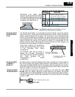
The figure below demonstrates how the OP-panel status register is mapped to user
memory for bit manipulation. Notice the sixteen bits in the status register are loaded
into the Internal Control Relays C0--C17. These control relays are used within the
ladder logic program for monitoring pushbuttons and coordinating data entry
control.
F5
F1
F2
F3
F4
Mapping the Status Register
V40600 =
V2014
C0 -- C17
M+12
M+12
Status register
SP1
V2014
V40600
LD
OUT
ON
OP-panel
Register
Internal
Control
Relays
SP1 (always ON) maps OP
register V2014 to
V40600:C0 --C17.
OP--640
M+12
12
13
14
15
8
9
10
11
4
5
6
7
0
1
2
3
C14
C15
C16
C17
C10
C11
C12
C13
C4
C5
C6
C7
C0
C1
C3 C2
PLC Program User Memory
F5
F1
F2
F3
F4
Mapping the Status
Register

