U
nd
er
st
an
di
ng
U
nd
er
st
an
di
ng
th
e
F
ea
tu
re
s
th
e
F
ea
tu
re
s
3--4
Installation and Specifications
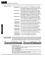
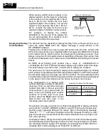
The following describes the function of each of the registers shown in the table.
S
Register M+0
-- When a number from 1 to 160 is placed in this register,
the predefined message associated with that number will
be displayed on the
top
line of the LCD display.
S
Register M+1
-- When a number from 1 to 160 is placed in this register,
the predefined message associated with that number
will be displayed on the
second
line of the LCD display.
S
Register M+2
-- When a number from 1 to 160 is placed in this register,
the predefined message associated with that number will
be displayed on the
third
line of the LCD display.
S
Register M+3
-- When a number from 1 to 160 is placed in this register,
the predefined message associated with that number
will be displayed on the
bottom
line of the LCD display.
S
Register M+4
-- This contains numeric data associated with the
top
line
display (this is described in more detail later).
S
Register M+5
-- This is used for long BCD and floating point data only.
S
Register M+6
-- This contains numeric data associated with the
second
line display (this is described in more detail later).
S
Register M+7
-- This is used for long BCD and floating point data only.
S
Register M+8
-- This contains numeric data associated with the
third
line display (this is described in more detail later).
S
Register M+9
-- This is used for long BCD and floating point data only.
S
Register M+10
-- This contains numeric data associated with the
bottom
line display (this is described in more detail later).
S
Register M+11
-- This is used for long BCD and floating point data only.
S
Register M+12
-- This is the Status Register (details below).
S
Register M+13
-- This is the Control Register (details below).
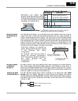
The Status register (M+12) and Control register (M+13) are used for data exchange
between the OP-panel and PLC program. The figure below shows the individual bits
within each data register. The function of the Status and Control register bits are
described below. Mapping these registers is covered at the end of this chapter.
Status Register M+12
LSB
F5
F1
F2
F3
F4
12
13
14
15
8
9
10
11
4
5
6
7
0
1
2
3
MSB
Control Register M13
LSB
LF2
LF3
BD
L1
L2
L3
LF1
12
13
14
15
8
9
10
11
4
5
6
7
0
1
2
3
MSB
Status Register (M+12):
F1--F5 -- Are the status function for the OP-panel definable pushbuttons. These bits
are set to 1 (ON) when the button is active.
Control Register (M+13):
L1--L3 -- Lamp ON/OFF control for each of the three lamp annunciators. Set to 1
(ON) to turn the lamp on.
LF1--LF3 -- Lamp Flash control for each of the three lamp annunciators. To flash the
lamp set Lamp and Lamp Flash bits both to 1 (ON).
BD-- Buzzer Disable. If set to 1 buzzer does not beep when buttons are pressed.
Register Definition
Status and Control
Register Definition


