S
ys
te
m
S
et
up
Yo
ur
P
an
el
C
on
fig
ur
in
g
P
ro
gr
am
m
in
g
E
xa
m
pl
es
5--4
Programming Examples
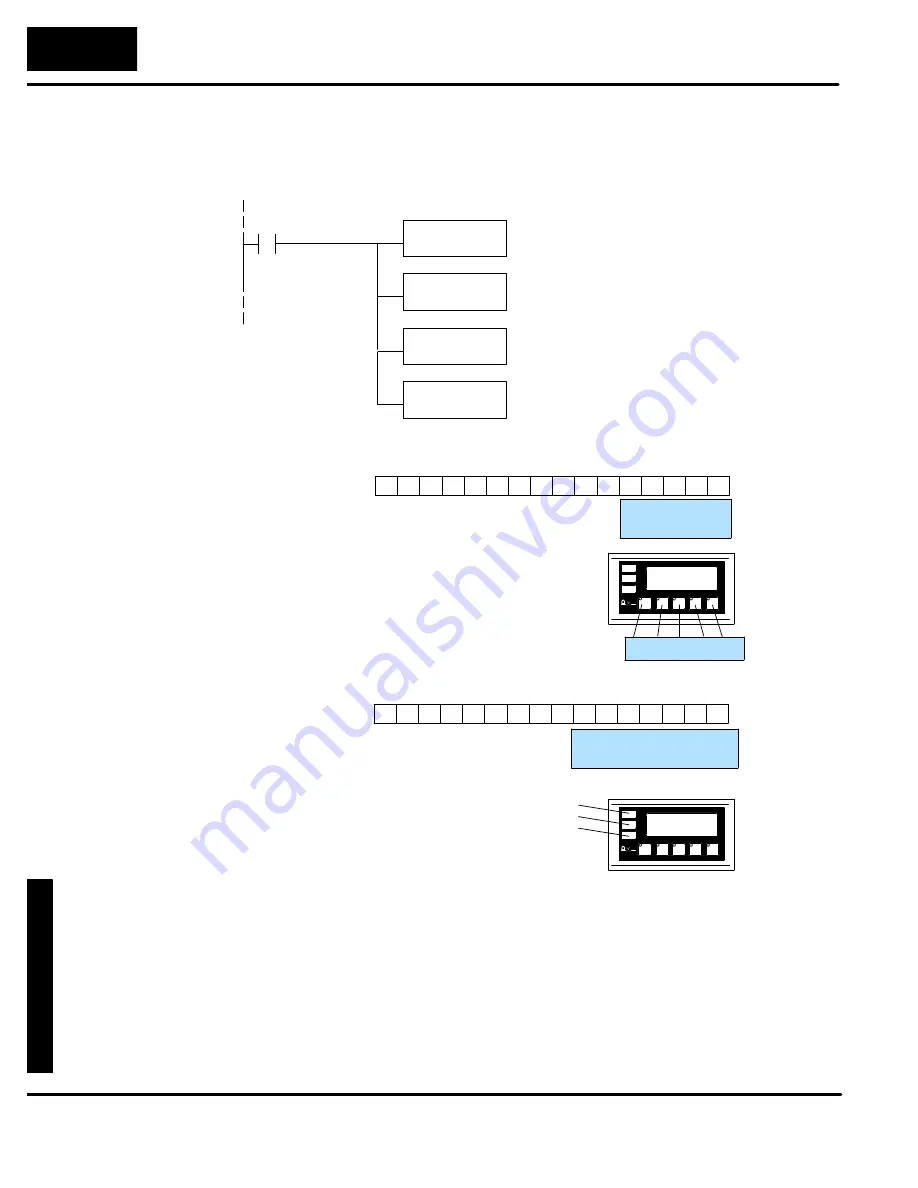
Place the following program rung in the program to copy the status register to
memory location V40600 and copy V40601 to the control register. With this rung
placed in the PLC program, the status and control bits will be control relays.
SP1
LD
V2014
OUT
V40600
Status register
LD
V40601
OUT
V2015
Control register
12 11
13
14
15
16
9
10
5
6
7
8
1
2
3
4
Status Register
F1
F2
F3
F4
12
13
14
15
8
9
10
11
4
5
6
7
0
1
2
3
LSB
MSB
Register V40600
Bit
C0
C1
C2
C3
As you can see, control relays C0--C4
will be associated with pushbuttons F1--F5.
F1 F2 F3 F4 F5
F5
C4
12 11
13
14
15
16
9
10
5
6
7
8
1
2
3
4
Control Register
12
13
14
15
8
9
10
11
4
5
6
7
0
1
2
3
LSB
MSB
Register V40601
Bit
L1
L2
L3
LF1
C20
C21
C22
C23
LF2
C24
C25
C26
LF3
BD
L1
L2
L3
Control relays C20--C22 will be associated
with lamps L1--L3.
Control relays C23--C25 will control
L1--L3 flashing. C26 controls whether
pushbuttons F1--F5 beep when pressed.


