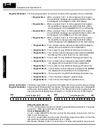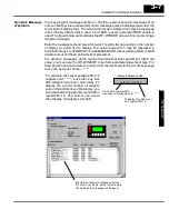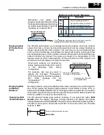
U
nd
er
sta
nd
in
g
th
e
F
ea
tu
re
s
3--13
Installation and Specifications
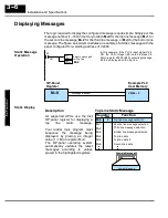
The lamp flash examples shown here are using
Direct
LOGIC PLC address
references. The equivalent instructions for
other
PLC products supported are shown
in Chapter 5.
V2015.4
C24
C21
C2
OUT
(DL250/D3--350/D4--450 Only)
OUT
In this example, C2 represents the pushbutton
No.3 (F3) via the mapping process. When
alter-
nating
pushbutton No.3 is pressed internal Con-
trol Relay C21 and C24 are energized ON. This
process manipulates Control register bit 1 and
bit 4 which controls yellow lamp and flashing.
*Control Register (M+13) = V40601: C20--C37
ON
ON
V2014.2
OUT
OUT
Direct bit register access
V2015.1
Memory Mapping Process
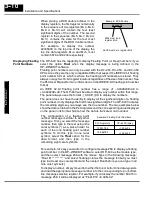
Each OP--640 is assigned 224 bits of PLC user memory which will be used as the
OP-panel database. The ladder logic program must access this assigned OP-panel
memory. Let’s take a closer look at this user memory and how it relates to the
OP-panel features.
As discussed earlier, regardless of which PLC product you are using the base
registers addressed M+0 through M+13 are formatted the same. In this manual,
when the terms M+0 through M+13 are used, this identifies which base register(s)
are affected for the topic being covered.
PLC user memory is assigned to each panel with the OP--WINEDIT configuration
software. For new OP-panels and add-on applications the programmer must define
fourteen 16-bit registers for PLC interface. Below is a figure showing memory layout
for
Direct
LOGIC DL05, DL105, DL205, D3--350, DL405 PLC’s and uses
V2000--V2015 for the OP--640 panel. See the next page for other PLC product
memory usage examples.
.
You must reserve 224 bits (fourteen
16-bit registers or twenty-eight 8-bit
registers) which are used to process data
between the panel and your PLC. You
must configure the
Base
register for the
OP-panel. This base register address is
stored in the OP-panel memory.
Total: 224 bits
CPU User’s memory
V2000
V2001
V2002
V2003
V2004
V2005
V2006
V2007
V2010
V2011
V2012
V2013
V2014
V2015
M+0
16 bits
M+1
16 bits
M+2
M+3
M+4
M+5
M+6
16 bits
16 bits
16 bits
16 bits
16 bits
M+7
16 bits
M+9
M+10
M+11
M+12
M+13
16 bits
16 bits
16 bits
16 bits
16 bits
M+8
16 bits
OP--640 Panel
Data Base
Lamp Flash
OP Base
Register Memory
Definition
Operator Panel
Base Memory

