6–RoCE Configuration
Configuring RoCE on the Adapter for Linux
78
AH0054601-00 B
Server Configuration
:
#
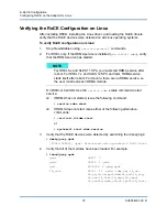
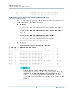
/sbin/ip link add link p4p1 name p4p1.100 type vlan id 100
#
ifconfig p4p1.100 192.168.100.3/24 up
#
ip route add 192.168.101.0/24 via 192.168.100.1 dev p4p1.100
Client Configuration:
#
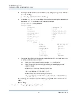
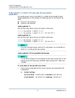
/sbin/ip link add link p4p1 name p4p1.101 type vlan id 101
#
ifconfig p4p1.101 192.168.101.3/24 up
#
ip route add 192.168.100.0/24 via 192.168.101.1 dev p4p1.101
2.
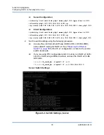
Set the switch settings using the following procedure.
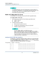
Use any flow control method (Pause, DCBX-CEE, or DCBX-IEEE),
and enable IP routing for RoCE v2. See
for RoCE v2 configuration, or refer to the vendor
switch documents.
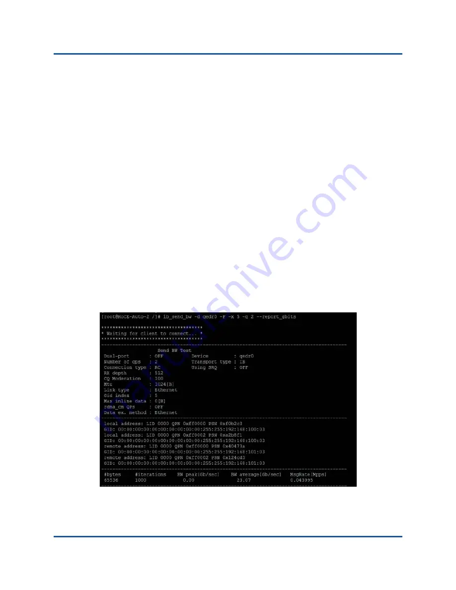
If you are using PFC configuration and L3 routing, run RoCE v2 traffic
over the VLAN using a different subnet, and use the RoCE v2 VLAN
GID index.
Server#
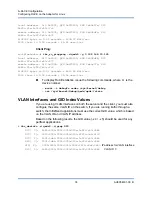
ib_send_bw -d qedr0 -F -x 5
Client#
ib_send_bw -d qedr0 -F -x 5 192.168.100.3
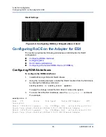
Server Switch Settings:
Figure 6-2. Switch Settings, Server

