D i d o H a r d w a r e M a n u a l
v . 1 . 0 . 5
Code Memory and Peripheral Booting. In order to fully
understand how boot work on DIDO platform, please refer to
Section 3.5 (Memory Map).
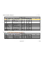
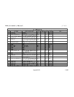
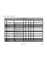
By default, DIDO provides the following configuration:
SYS_BOOT
pin
Default
Value
Function
Configurable
BTMODE[15]
0
GPMC CS0 Wait enable
NO
BTMODE[14:13]
10
GPMC CS0
Address/Data
multiplexing mode
NO
BTMODE[12]
1
GPMC CS0 bus width
NO
BTMODE[11]
0
RSTOUT_WD_OUT
Configuration
NO
BTMODE[10]
0
XIP (on GPMC) Boot
Options
NO
BTMODE[9:8]
01
Ethernet PHY Mode
Selection
NO
BTMODE[7:5]
000
Reserved
NO
BTMODE[4:0]
10111
Boot Mode Order
YES
Bootstrap pins BTMODE[4:0] are routed to main connectors in
order to allow to change bootstrap strategy in user's
application by optional external circuitry.
5.5.1
Default boot configuration
With the default configuration, the boot sequence is:
1. MMC
2. SPI
3. UART
4. EMAC
The internal BootROM tries each boot mode in sequence and
stops when it find a valid boot code. For example, assuming
that:
1. default configuration is not changed,
2. no boot MMC card is connected to processor's MMC1
interface,
August, 2014
26/78


