4-38
Chapter 4
For parameter configuration
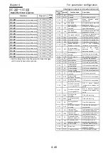
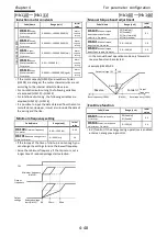
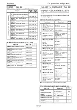
[CA-60]
~
[CA-84]
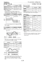
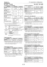
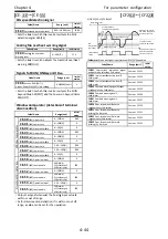
[FUP]/[FDN] operations
Code/Name
Range (unit)
Initial
value
CA-60
FUP/FDN overwrite
target selection
00(Speed reference)
01(PID)
00
CA-61
FUP/FDN data save
enable
00(No save)/
01(Save)
00
CA-62
UDC terminal mode
selection
00(0Hz)/
01(Save data)
00
CA-64
Acceleration time for
FUP/FDN function
0.00
~
3600.00(s)
30.00
CA-66
Deceleration time for
FUP/FDN function
30.00
・
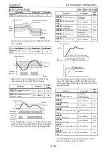
[CA-60] sets as operation target the frequency reference
or the PID target value for 020[FUP]/021[FDN].
・
[CA-61] sets if the modified values of [FUP] / [FDN]
should be saved or not in the storage memory.
・
[CA-62] selects the frequency in which will change the
frequency reference for when [UDC] terminal is ON.
・
If [FUP]/[FDN] is turn ON, in the case the frequency
reference is changed
you can set the acceleration and
deceleration time [CA-64][CA-66].
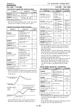
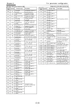
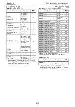
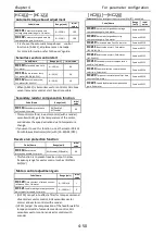
[F-OP] Speed/Operation change
Code/Name
Range (unit)
Initial
value
CA-70
Speed command
selection when [F-OP] active
01
~
03
、
07
、
08
、
12
、
14
、
15 *1)
01
CA-71
Operation command
reference selection when
[F-OP] active
00
~
03 *2)
01
・
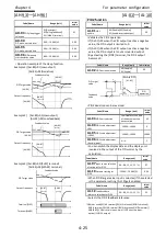
If Intelligent input terminal 023[F-OP] is ON the change
is carried out.
*1)01(Ai1 terminal)/02(Ai2 terminal)/03(Ai3 terminal)/ 07(Parameter)/ 08(RS485)/
12(Pulse train input:main)/14(EzSQ function)/15(PID result)
*2) 00([FW]/[RV] terminal)/01(3-wire)/02(Keypad’s RUN key)/03(RS485)
Reset terminal [RS]
Code/Name
Range (unit)
Initial
value
CA-72
Reset mode
selection
00(Trip release at turn-ON)/
01(Trip release at turn-OFF)/
02(Effective only in trip ON condition)/
03(Effective only in trip OFF condition)
00
・
Output is shut off when reset terminal is ON.
This terminal is valid only while in trip status.
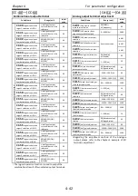
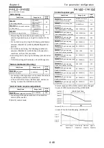
Main encoder input
Code/Name
Range (unit)
Initial value
CA-81
Encoder constant setting
0
~
65535(Pls)
1024
CA-82
Encoder phase selection
00(Phase A precedent)/
01(Phase B precedent)
00
CA-83
Numerator of the
motor gear ratio
1
~
10000
1
CA-84
Denominator of the
motor gear ratio
1
~
10000
1
・
Sets the main encoder input and the motor gear ratio
involved in the encoder feedback.
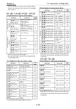
[CA-90]
~
[CA-99]
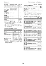
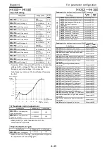
Pulse train input terminal
Code/Name
Range (unit)
Initial
value
Pu
ls
e
tr
ai
n
in
pu
t
(m
ai
n)
CA-90
Pulse train detection
object selection
00(Frequency reference)/
01(Pulse count)/
02(Speed
feedback
:
sensor-V/f)
00
CA-91
Mode selection of
pulse train input
00(90º-phase-shift)/
01(Forward/reverse
operation and direction of
rotation)/
02(Forward/reverse
operation with pulse train)
00
Pu
ls
e
tr
ai
n
fr
eq
ue
nc
y
(m
ai
n)
CA-92
pulse train
frequency Scale
0.05
~
32.0(kHz)
25.0
CA-93
pulse train
frequency filter time
constant
0.01
~
2.00(s)
0.10
CA-94
pulse train
frequency Bias value
-100.0
~
100.0(%)
0.0
CA-95
Pulse train
frequency high limit
0.0
~
100.0(%)
100.0
CA-96
Pulse train
frequency detection
Low level
0.0
~
100.0(%)
0.0
・
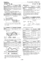
A pulse train is introduced in functions [PLA][PLB]
assigned to terminals A,B. If [CA-90]=01, pulses in
terminals A & B are counted. Only terminal A in case
that is a single phase input.
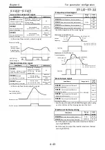
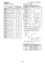
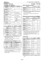
Pulse train counter
Code/Name
Range (unit)
Initial
value
CA-97
Comparing match output
ON-level for pulse count
0
~
65535
0
CA-98
Comparing match output
OFF-level for pulse count
0
~
65535
0
CA-99
Comparing match output Maximum value
for pulse count
0
~
65535
65535
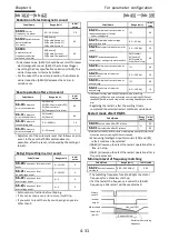
・
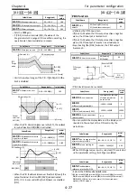
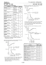
Set 091[PCMP] to output the compare results of the
pulse train counters of functions 103[PLA]/104[PLB].
・
Turning 097[PCC] terminal in ON state resets the
counter.
・
In the following example, when [CA-81]=01, inputting a
pulse train in terminal A.
Internal counter
0
Max. count value
[CA-79]
OFF level [CA-78]
ON level [CA-77]
[PLA] input
[PCC] input
[PCMP] output
Summary of Contents for P1-00041HFEF
Page 6: ...0 5 Contents Contents Memo ...
Page 42: ...2 26 Chapter 2 Installation and Wiring Memo ...
Page 129: ...Index Index 3 memo ...
Page 130: ...Index Index 4 memo ...

