4-22
Chapter 4
For parameter configuration
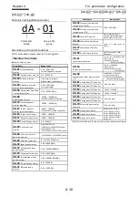
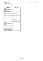
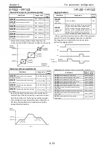
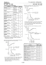
[AH-01]
~
[AH-06]
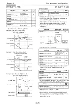
PID1 function
Code/Name
Range (unit)
Initial value
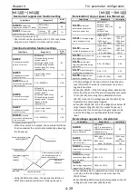
AH-01
PID1 enable
00(Disable)/
01(Enable)/
02(Enable:inverted output)
00
・
Validates the PID1 operation.
・
If [AH-01]=01 when the PID output reaches negative
value, the PID output is limited to 0.
・
If [AH-01]=02 when the PID output reaches negative
value, the PID output lets out an inverted output.
・
When the PID output is negative, the motor will rotate
in the contrary direction.
・
If [PID] terminal is ON, the PID control is disabled and
the [PID] target value becomes the frequency
reference.
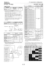
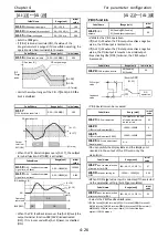
Code/Name
Range (unit)
Initial value
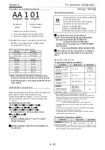
AH-02
PID1 deviation inverse
00(Disable)/
01(Enable)
00
Code/Name
Range (unit)
Initial
value
AH-03
unit selection for PID1
<unit table> at the end
of the document can
be consulted
03
AH-04
PID1 adjustment (0%) -10000
~
10000
0
AH-05
PID1 adjustment
(100%)
-10000
~
10000
10000
AH-06
PID1 Adjustiment
(decimal point)
0
~
4
2
・
The unit and display data related to the output of the
PID control can be changed.
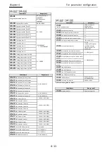
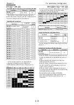
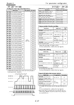
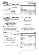
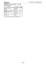
[AH-07]
~
[AH-50]
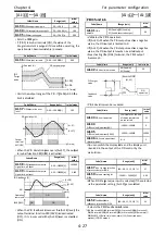
Code/Name
Range (unit)
Initial
value
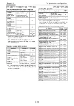
AH-07
Target value 1 reference
selection for PID1
00
~
06/09
~
15
*1)
09
AH-10
PID1 target value-1
0.00
~
100.00(%)
*1)
0.00
AH-12
PID1 Multistage set point 1
0.00
AH-14
PID1 Multistage set point 2
0.00
AH-16
PID1 Multistage set point 3
0.00
AH-18
PID1 Multistage set point 4
0.00
AH-20
PID1 Multistage set point 5
0.00
AH-22
PID1 Multistage set point 6
0.00
AH-24
PID1 Multistage set point 7
0.00
AH-26
PID1 Multistage set point 8
0.00
AH-28
PID1 Multistage set point 9
0.00
AH-30
PID1 Multistage set point 10
0.00
AH-32
PID1 Multistage set point 11
0.00
AH-34
PID1 Multistage set point 12
0.00
AH-36
PID1 Multistage set point 13
0.00
AH-38
PID1 Multistage set point 14
0.00
AH-40
PID1 Multistage set point 15
0.00
AH-42
Input source selection of Set
point 3 for PID1
00
~
13*2)
00
AH-44
PID1 target value-2
0.00
~
100.00(%)
0.00
AH-46
Target value 3 reference
selection for PID1
00
~
13*2)
0.00
AH-48
PID1 target value-3
0.00
~
100.00(%)
0.00
AH-50
Math operator selection of
PID1 target value 1
01(Addition)
02(Subtraction)
03(Multiplication)
04(Division)
01
*1) Display range can be set by [AH-04], [AH-05] and [AH-06].
*2) 00(Disabled)/01(Ai1 terminal)/02(Ai2 terminal)/
03(Ai3 terminal)/07(Parameter)/08(RS485)/14(Pulse train
input:main)/
・
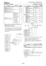
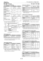
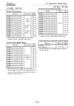
For PID1 target value, two targets are selected, target value 1 and
target value 2, the result of the operation carried out between these
two targets constitutes the PID1 target value.
・
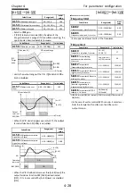
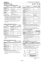
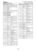
If Input terminal function 051[SVC1]
~
054[SVC4] are used, the PID
target value can be changed for the Multistage.
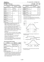
Multistage value
SVC4
SVC3
SVC2
SVC1
Target value 0
OFF
OFF
OFF
OFF
Target value 1
OFF
OFF
OFF
ON
Target value 2
OFF
OFF
ON
OFF
Target value 3
OFF
OFF
ON
ON
Target value 4
OFF
ON
OFF
OFF
Target value 5
OFF
ON
OFF
ON
Target value 6
OFF
ON
ON
OFF
Target value 7
OFF
ON
ON
ON
Target value 8
ON
OFF
OFF
OFF
Target value 9
ON
OFF
OFF
ON
Target value 10
ON
OFF
ON
OFF
Target value 11
ON
OFF
ON
ON
Target value 12
ON
ON
OFF
OFF
Target value 13
ON
ON
OFF
ON
Target value 14
ON
ON
ON
OFF
Target value 15
ON
ON
ON
ON
PID
operation
PID target value
Feedback
+
00
01
+
-
Reverse PID1
[AH-02]
-
PID1
target value
PID1 target [AH-10]
RS485
communication
Option 1
Option 2
Option 3
[AH-07]
Multistage target 1
~
15
Analog input 1
Analog input 2
Analog input 3
Not used
[SVC1-4]
[AH-50]
+, -, x, ÷
[AH-42]
01
02
03
09
10
11
12
13
00
PID1 target [AH-44] 09
01
00
Summary of Contents for P1-00041HFEF
Page 6: ...0 5 Contents Contents Memo ...
Page 42: ...2 26 Chapter 2 Installation and Wiring Memo ...
Page 129: ...Index Index 3 memo ...
Page 130: ...Index Index 4 memo ...

