____________________________________________________________________________________
____________________________________________________________________________________
Speeder X1 and X2 Configuration and API Guide
Page 15/36
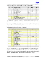
Advanced configuration parameters for above the road operation:
No.
Type
Name / Description
Unit
Range
Default
14
B
Trigger Window Width
dm
1 - 255
51
15
B
Hits For Trig
smpls
1 - 255
10
17
B
Trigger Length (Note 3)
ms
1 - 255
255
18
B
Clear Check Time
10 ms
0 - 255
30
31
B
Speed Calculation Start
dm
0 - 10
0
36
B
Speed Limit Large
km/h
0
37
B
Speed Limit
km/h
0
39
W
Vehicle Height Limit
cm
0
45
B
Classification Window
dm
40 - 255
40
46
B
Speed Verification Distance
dm
0 - 255
0
51
B
Control Byte 5
b5
Speed Verification Digital IO Control
0
b7
Trigger From Beam A (Note 4)
0
Note 3: Setting Trigger Length = 255 keep the trigger active until vehicle has passed the measurement
point.
Note 4: Beam that sets trigger output signal (DIGOUT) can be selected for approaching vehicles. When
this bit is set trigger will occur when vehicle is detected by Beam A. In case bit is cleared or Speed limit is
set trigger will occur when vehicle is detected by Beam B.
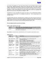
Following information may be added to the result:
No.
Type
Name / Description
Unit
Range
Default
2
B
Control Byte 1
b0
Profile Measurement
0
b7
Vehicle Size (Note 5)
0
26
B
Control Byte 3
b1
Disable Ok Text
0
b2
Speed Output 0: km/h 1: MPH
0
b3
Show Speed Histogram
0
b7
Vehicle Height
0
48
B
Snow Ground Distance
cm
0 - 38000
0
50
B
Control Byte 4
b0
Trigger Time Output
0
b1
Trigger Time Interval
0
b2
Trigger Occupancy Time
0
b3
Traffic Flow
0
b4
Count Output
0
b6
CSV output
1
51
B
Control Byte 5
b2
Show Violation Only
0
b3
Measure Amount Of Snow Fall
0
b4
Show Speed Error Byte
0
Note 5: The vehicle size (length) is an estimation based on the speed and the time the sensor is able to
get results from a vehicle. This principle generates longer value for higher vehicle than its real length is.
Note! In this mode the sensor will send
the message ”OK” once a minute if the sensor is
functional (the message can be disabled by Bit 1 of Control Byte 3, par. 26).


