____________________________________________________________________________________
____________________________________________________________________________________
Speeder X1 and X2 Configuration and API Guide
Page 11/36
3 DISTANCE MEASUREMENTS
3.1 ASCII Mode
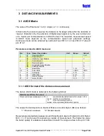
The value of the Parameter 1 is 0 (= single) or 1 (= continuous).
In this mode the sensor measures the distance to the target either after the detection of
<space> character or by the activation of Digital-input-signal or by the user command (c
or C). Serial port communication is in ASCII format. The maximum measurement speed
in ASCII mode depends on the communication speed and parameter settings.
Continuous mode can be activated by command <esc>M1<cr> or <esc>M<cr> if value of
par. #1 is 1.
Parameters related to ASCII mode are:
No.
Type
Name / Description
Unit
Range
Default
1
B
Operation Mode
0 or 1
2
B
Control Byte 1
b4
Hardware Input Disable
0
3
B
Control Byte 2
b2
Decimal Enable
0
b3
Amplitude Output Enable
1
b5
Fast Key Disable
0
4
B
Baud Rate
1 - 10
4
5,6
W
Pulse Rate
Hz
1-2000
2000
7
B
Averaging
2
n
0 - 14
4
8
B
Attenuation
0 - 15
0
11
B
Device Number
0 - 9
0
47
B
Laser Control
0,1,2
2
3.1.1 ASCII format of the distance measurement
The data in ASCII mode is delivered in the following format:
Distance result from the sensor
Dzxxxxx[.d]<space>[aaaaa]<cr><lf> z
is automatically added number for values > 99m
xxxxx is distance in millimetres,
.d
is the decimal digit (option),
aaaaa is the signal amplitude value (option)
The answer format depends on Decimal Enable in Control Byte 2 (Bit 2) as follows:
“1”: Dxxxxx.x aaaaa.a
“0”: Dxxxxx aaaaa
Received signal amplitude (aaaaa) is sent if Amplitude Output is Enabled (Control Byte 2,
Bit 3 = 1). It can be used for analyzing a quality of measurement. The higher the value,
the better quality of a distance measurement result. The range is a few tens up to 1300.


