____________________________________________________________________________________
____________________________________________________________________________________
Speeder X1 and X2 Configuration and API Guide
Page 7/36
O<0/1>
0 = pointer OFF, 1 = pointer ON
OOK
P<No.>
Read the value in EPROM of the parameter No.
Pxxxxx
S
Save user parameters to permanent memory
(X must be used before)
SOK
T<No.>,<Value>
Write <Value> to the parameter <No.> (ram)
TOK
TW<No.>,<Value
Write integer <Value> (0-65535) to parameter <No.>
and <No.>+1
TOK
v (lower case)
Sensor information in the Noptel internal format
V (upper case)
Sensor information in ASCII format (version)
Sensor information
4)
V1
Read voltage, current and temperature measurements
Table
5)
V2
Perform self-test and show its result
OK or
Explanation of the
error and ERR:xxxxx
X
Enable writing to permanent memory
WR ENABLE
Commonly used commands in configuring the sensor for applications are light blue.
The end of the line of answer is always <cr><lf>.
1)
Distance measurement commands
Commands c and C, return results according to Chapter 3.1.
With command H it
’s the same except Amplitude Output Enable does not have an effect
but amplitude is given in any case.
2)
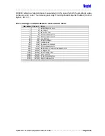
Error table (example) (table is for diagnostic purposes only and it is updated
during every power-up of the sensor)
Code
Error
Error count
0001
EEPROM R/W
:
0
0002
TDC datardy
:
0
0004
RX Error
:
0
0008
TDC main counter
:
0
0010
TDC interpolator
:
0
0020
Low battery
:
0
0040
Supply voltage!
:
0
0080
Invalid value
:
0
0100
Unknown command
:
0
0200
TDC interp zero
:
0
0400
EEPROM/FLASH:CRC?
:
0
0800
Voltage error!
:
0
1000
APD voltage!
:
0
2000
Temperature!
:
0
4000
Power consumption!
:
0
8000
HV error!
:
0
OK
Some errors may occur in certain conditions, like too low supply voltage or too high/low
operating temperature. If the operation of the sensor returns to normal and errors do not
keep increasing, it is safe to continue using the sensor. Otherwise contact Noptel Oy for
further information.


