____________________________________________________________________________________
____________________________________________________________________________________
Speeder X1 and X2 Configuration and API Guide
Page 22/36
The size calculation is based on the time the vehicle is detected, which causes an effect
that a closer vehicle is estimated to be bigger than a far one even though the actual length
of the vehicles is the same. The speed measurement principle itself and the output of the
sensor are identical to the mode 7 (Speed measurement mode).
4.3 Automatic setting of the measurement window
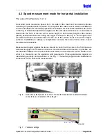
Speeder X1 includes a function that helps the user to set up the triggering window at a
correct distance. The function is designed to be used with both Speed measurement
modes, vertical measurement (#7) and horizontal measurement (multiple lanes)(#12).
Calibration is carried out for both approaching and departing vehicles. For approaching
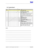
vehicles bit 5 of Control Byte 1 (par. 2) must be cleared. Calibration is started with
command “U”.
To calibrate the triggering window for the departing vehicles bit 5 of Control Byte 2 (Speed
Behind) must be set. A complete calibration cycle requires 12 vehicles to pass the
measurement area. Two vehicles are used to evaluate the orientation of the sensor and
10 to detect correct measurement window.
When orientation of the sensor is unknown to user it is possible to set parameter 53 to
value 0. Function detects the orientation of the sensor before setting up the measurement
window. When the parameter setting and orientation detection are opposite user is
informed before changing the setting.
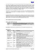
The sensor will guide the user through the calibration procedure. Setting up the calibration
is shown in the next paragraphs with example outputs for both measurement modes.
4.3.1 Vertical setup
Before entering the vertical setup mode the sensor must be aimed correctly. Make sure
that the height of the sensor is set correctly [parameter 32, Speed geometry (height from
the ground in decimeters)]. Furthermore, please check that the parameter 43 is set as
zero. Orientation of the sensor is set by parameter 53. Default setting (53 = 1) is such
that laser radiation sticker side of the sensor is set up.
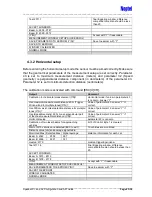
The calibration mode is activated with command [ESC]U[CR].
Output
Comment
Using height (SpeedGeometry) 600 cm (Y/N)
Verify or change
Vertical setup
parameter 43 is zero
Calibration of two laser beams for approaching vehicles
bit 5 of Control Byte 1 is cleared
Wait until 10 vehicles are detected (ESC to exit)
10 vehicles are monitored
Distance value [cm] and average signal table:
Monitored Max | Detected Max | Signal average
distance information for each car
Beam A: 2764 | 2721 | 397
Beam B: 2696 | 2660 | 235
median: 2566
median triggering window


