16
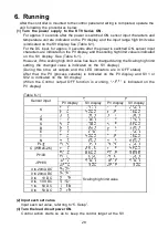
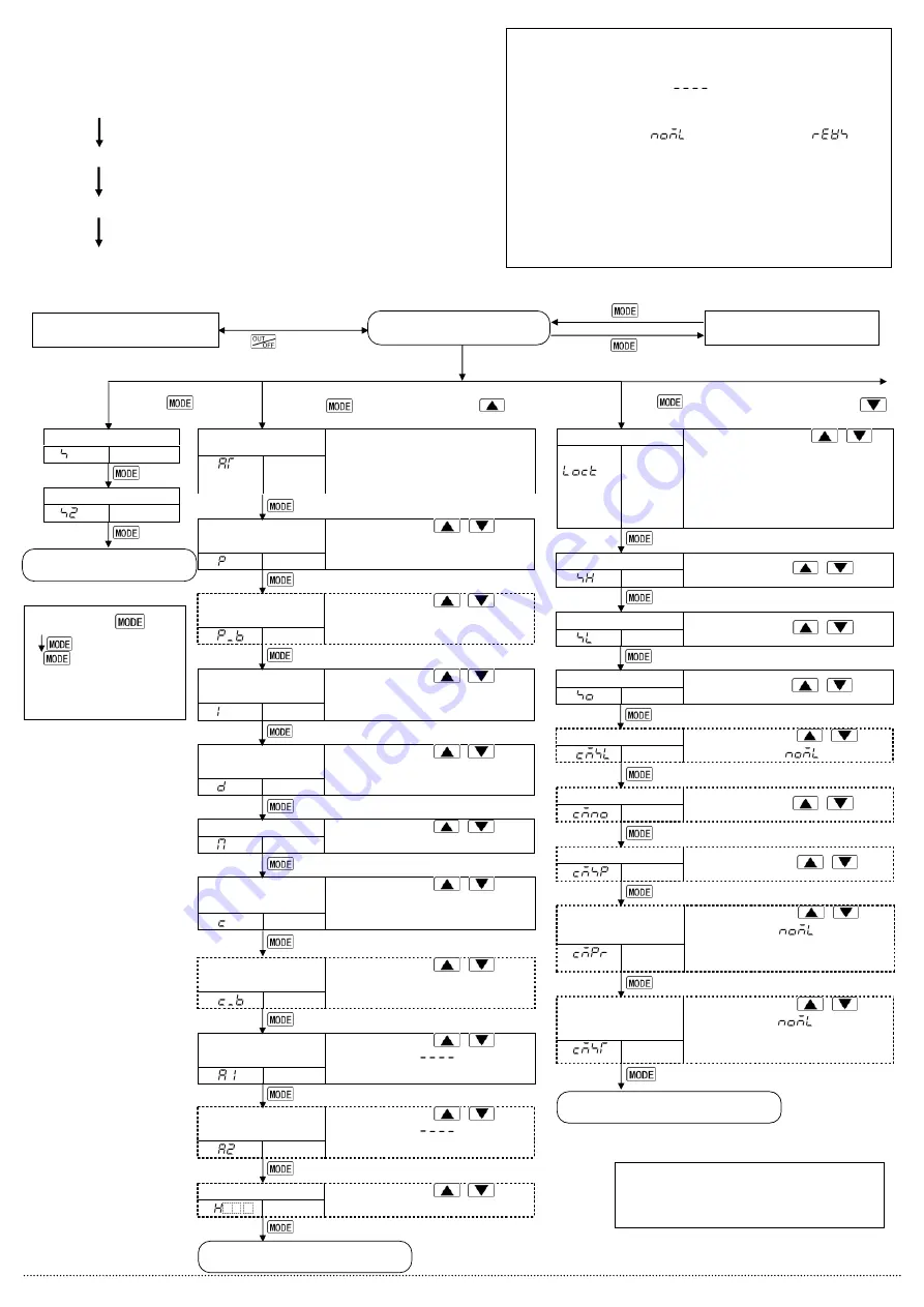
5.1 Operation flow chart
Outline of operation procedure
Operation before running
[Step 1
Initial setting]
: Set Input type, Alarm type, control action,
etc. in Auxiliary function setting mode 2.
[Step 2
Adjusting item]
: Set PID values and Alarm values in the
Sub setting mode.
[Step 3
Lock setting]
: Set the Set value Lock, SV high limit and SV low
limit in Auxiliary function setting mode 1 (If Step 3
is not necessary, skip this step.)
[Step 4
Run setting]
: Set SV1 (desired value) in the Main setting mode.
Set value Lock
PV
SV
Selection
• Make a selection with
,
keys.
• If Lock 1 or Lock 2 is selected,
AT or Auto-reset does not work.
• Be sure to select Lock 3 when
using Serial communication.
[Auxiliary function setting mode 1]
AT/Auto-reset
PV
SV
Selection
• If AT is cancelled during the process,
PID values revert to previous value.
• Auto-reset is automatically cancelled
in 4 minutes.
SV1 (Desired value)
PV
SV
SV
OUT2 proportional
band
PV
SV
Set value
• Set the value with
,
keys.
• Available when Heating/Cooling
control (OUT2) is added
Integral time
PV
SV
Set value
• Set the value with
,
keys.
• PD action when set to 0, and auto-
reset can be performed.
OUT1 proportional
band
PV
SV
Set value
• Set the value with
,
keys.
• ON/OFF action when set to 0 or 0.0
Derivative time
PV
SV
Set value
• Set the value with
,
keys.
• PI action when set to 0
OUT1 proportional
cycle
PV
SV
Set value
• Set the value with
,
keys.
• Not available for DC current output or
when OUT1 is ON/OFF action
OUT2 proportional
cycle
PV
SV
Set value
• Set the value with
,
keys.
• Not available for DC current output or
when OUT2 is ON/OFF action
ARW
PV
SV
Set value
• Set the value with
,
keys.
• Available for PID action
A1 value
PV
SV
Set value
• Set the value with
,
keys.
• Not available if
is selected
during A1 type selection
Heater burnout alarm value
PV
.
SV
Set value
• Set the value with
,
keys.
• OFF when set to 0.0
A2 value
PV
SV
Set value
• Set the value with
,
keys.
• Not available if
is selected
during A2 type selection
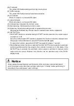
Reverts to the PV/SV display.
Reverts to PV/SV display.
Press the
key.
[Main setting mode]
[Sub setting mode]
(5)
PV/SV display
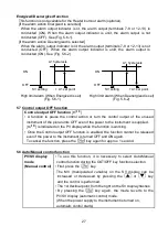
Control output OFF function or
Auto/Manual control function
Press
key for approx. 1sec.
Output MV indication
Explanation of
key
: This means that
if
is pressed, the set
value is saved, and the
controller proceeds to the
next setting item.
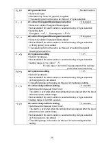
Alarm 1 (A1) setting procedure
[Numbers (1) to (5) are indicated on the flow chart.]
(1) [A1 type]: Select an alarm type
[If an alarm type except for
is selected, items (2) to (5)
are indicated and they can be set if necessary.]
(2) [A1 action Energized/Deenergized]: Select Alarm 1 contact
output ON (Energized:
) or OFF (Deenergized:
).
(3) [A1 hysteresis]: Set A1 hysteresis.
(4) [A1 action delayed timer]: Set A1 action delayed time.
(If input enters alarm action range and setting times has passed,
the alarm is activated.)
(5) [A1 value]: Set action point of A1 output.
[Note]
If an alarm type is changed, the alarm set value
becomes 0 (0.0). Therefore it is necessary to reset it.
Setting items with dotted lines are optional
and they appear only when the options are
added.
SV low limit
PV
SV
Set value
• Set the value with
,
keys.
SV high limit
PV
SV
Set value
• Set the value with
,
keys.
Sensor correction
PV
SV
Set value
• Set the value with
,
keys.
Communication protocol
PV
SV
Selection
•
Make a selection with
,
keys.
• Not available for
indication
Instrument number
PV
SV
Set value
• Set the value with
,
keys.
Communication speed
PV
SV
Selection
•
Make a selection with
,
keys.
Stop bit
PV
SV
Selection
•
Make a selection with
,
keys.
• Not available if
is selected
during Communication protocol
selection
Parity
PV
SV
Selection
•
Make a selection with
,
keys.
• Not available if
is selected
during Communication protocol
selection
Reverts to the PV/SV display.
Press the
while holding down the
key.
Press the
key.
Press the
key
for approx. 3sec.
Press
for approx. 3sec while holding down
.
SV2 (Desired value)
PV
SV
SV

