vii
S7-200 Programmable Controller, CPU 210
C79000-G7076-C235-01
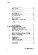
3.8
Downloading and Monitoring the Sample Program
3-23
. . . . . . . . . . . . . . . . . . . . . . . . . . .
Downloading the Project to the PDS 210
3-23
. . . . . . . . . . . . . . . . . . . . . . . . . . . . . . . . . . .
Using the Ladder Editor to Monitor the Status of the Program
3-23
. . . . . . . . . . . . . . . . .
Using the Status Chart to Monitor and Modify the Current Values of the Program
3-24
3.9
Modifying the Sample Program
3-25
. . . . . . . . . . . . . . . . . . . . . . . . . . . . . . . . . . . . . . . . . . .
Creating the Blink Patterns for the LED
3-25
. . . . . . . . . . . . . . . . . . . . . . . . . . . . . . . . . . . .
Turning the LED On and Off
3-26
. . . . . . . . . . . . . . . . . . . . . . . . . . . . . . . . . . . . . . . . . . . . . .
4
Basic Concepts for Programming the CPU 210
4.1
Guidelines for Designing a Micro PLC System
4-2
. . . . . . . . . . . . . . . . . . . . . . . . . . . . . .
Partitioning Your Process or Machine
4-2
. . . . . . . . . . . . . . . . . . . . . . . . . . . . . . . . . . . . . .
Creating the Functional Specifications
4-2
. . . . . . . . . . . . . . . . . . . . . . . . . . . . . . . . . . . . .
Designing the Safety Circuits
4-3
. . . . . . . . . . . . . . . . . . . . . . . . . . . . . . . . . . . . . . . . . . . . .
Specifying the Operator Stations
4-3
. . . . . . . . . . . . . . . . . . . . . . . . . . . . . . . . . . . . . . . . . .
Creating the PLC Configuration Drawings
4-3
. . . . . . . . . . . . . . . . . . . . . . . . . . . . . . . . . .
Creating a List of Symbolic Names
4-3
. . . . . . . . . . . . . . . . . . . . . . . . . . . . . . . . . . . . . . . .
4.2
Concepts for Creating a Program
4-4
. . . . . . . . . . . . . . . . . . . . . . . . . . . . . . . . . . . . . . . . .
Relating the Program to Inputs and Outputs
4-4
. . . . . . . . . . . . . . . . . . . . . . . . . . . . . . . .
Accessing Data in the Memory Areas
4-4
. . . . . . . . . . . . . . . . . . . . . . . . . . . . . . . . . . . . . .
Organizing the Program
4-5
. . . . . . . . . . . . . . . . . . . . . . . . . . . . . . . . . . . . . . . . . . . . . . . . .
4.3
Understanding the Scan Cycle of the CPU 210
4-6
. . . . . . . . . . . . . . . . . . . . . . . . . . . . .
Understanding the Basic Scan Cycle of the CPU 210
4-6
. . . . . . . . . . . . . . . . . . . . . . . .
Understanding the Basic Scan Cycle of the PDS 210
4-7
. . . . . . . . . . . . . . . . . . . . . . . .
Using the Debug Option to Specify the Number of Scans
4-8
. . . . . . . . . . . . . . . . . . . . .
4.4
Understanding the Programming Languages
4-9
. . . . . . . . . . . . . . . . . . . . . . . . . . . . . . .
Understanding the Basic Elements of Ladder
4-9
. . . . . . . . . . . . . . . . . . . . . . . . . . . . . . .
Understanding the Statement List Instructions
4-10
. . . . . . . . . . . . . . . . . . . . . . . . . . . . . .
4.5
Understanding the Addresses of the Memory Areas
4-11
. . . . . . . . . . . . . . . . . . . . . . . . .
Using the Memory Address to Access Data
4-11
. . . . . . . . . . . . . . . . . . . . . . . . . . . . . . . . .
Addressing the Input Image Register (I)
4-12
. . . . . . . . . . . . . . . . . . . . . . . . . . . . . . . . . . . .
Addressing the Outputs (Q)
4-12
. . . . . . . . . . . . . . . . . . . . . . . . . . . . . . . . . . . . . . . . . . . . . .
Addressing the Bit Memory (M) Area
4-12
. . . . . . . . . . . . . . . . . . . . . . . . . . . . . . . . . . . . . .
Addressing the Special Memory (SM) Bits
4-12
. . . . . . . . . . . . . . . . . . . . . . . . . . . . . . . . . .
Addressing the Timer (T) Memory Area
4-13
. . . . . . . . . . . . . . . . . . . . . . . . . . . . . . . . . . . .
Addressing the Counter (C) Memory Area
4-13
. . . . . . . . . . . . . . . . . . . . . . . . . . . . . . . . . .
Using Constant Values
4-13
. . . . . . . . . . . . . . . . . . . . . . . . . . . . . . . . . . . . . . . . . . . . . . . . . .
4.6
Sample Program Using an Interrupt Routine
4-14
. . . . . . . . . . . . . . . . . . . . . . . . . . . . . . . .
4.7
Using the Analog Adjustment Potentiometer
4-16
. . . . . . . . . . . . . . . . . . . . . . . . . . . . . . . .
5
Instruction Set
5.1
Valid Ranges for the CPU 210 and PDS 210
5-2
. . . . . . . . . . . . . . . . . . . . . . . . . . . . . . . .
Valid Operand Ranges
5-2
. . . . . . . . . . . . . . . . . . . . . . . . . . . . . . . . . . . . . . . . . . . . . . . . . .
5.2
Contact Instructions
5-3
. . . . . . . . . . . . . . . . . . . . . . . . . . . . . . . . . . . . . . . . . . . . . . . . . . . . .
Standard Contacts
5-3
. . . . . . . . . . . . . . . . . . . . . . . . . . . . . . . . . . . . . . . . . . . . . . . . . . . . . .
Not
5-3
. . . . . . . . . . . . . . . . . . . . . . . . . . . . . . . . . . . . . . . . . . . . . . . . . . . . . . . . . . . . . . . . . . .
Positive, Negative Transition
5-3
. . . . . . . . . . . . . . . . . . . . . . . . . . . . . . . . . . . . . . . . . . . . .
Compare Word Integer
5-4
. . . . . . . . . . . . . . . . . . . . . . . . . . . . . . . . . . . . . . . . . . . . . . . . . .
Contact Examples
5-4
. . . . . . . . . . . . . . . . . . . . . . . . . . . . . . . . . . . . . . . . . . . . . . . . . . . . . .
Output
5-5
. . . . . . . . . . . . . . . . . . . . . . . . . . . . . . . . . . . . . . . . . . . . . . . . . . . . . . . . . . . . . . . .
Set, Reset
5-5
. . . . . . . . . . . . . . . . . . . . . . . . . . . . . . . . . . . . . . . . . . . . . . . . . . . . . . . . . . . . .
Contents
Summary of Contents for Simatic S7-200 CPU 210
Page 10: ...x S7 200 Programmable Controller CPU 210 C79000 G7076 C235 01 Contents ...
Page 116: ...A 16 S7 200 Programmable Controller CPU 210 C79000 G7076 C235 01 CPU 210 Data Sheets ...
Page 126: ...F 2 S7 200 Programmable Controller CPU 210 C79000 G7076 C235 01 CPU 210 Order Numbers ...
Page 138: ...Index 12 S7 200 Programmable Controller CPU 210 C79000 G7076 C235 01 Index ...


